
 Tonight I finally could make progress on the axle bearings. Until now I scratched my head on how to realize the bearings and especially the connection between the leaf springs and frame in a way that supplies both prototypically accurate and solid results – without purchasing a lathe and mill.
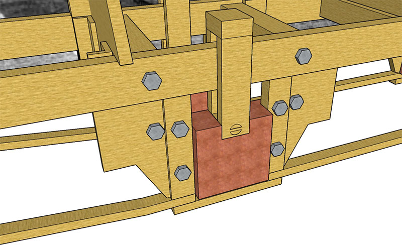
The first image shows the basic concept: two plates (how are they named in english, please?) are going to be brazed to the frame bars, which are also going to be reinforced on the inner side of the frame. I’ll say more on that on a later post. On these plates I want to attach two slides to guide the axle bearings. I’m planning to use screws to fasten these slides, so I can replace them if need be. Between these slides the actual bearing should be cut and filed from a piece of copper to accomodate the axle. On top of the bearing I’m planning to braze a piece of four-sided brass which will serve as a connection to the spring support. The latter could either be made out of solid foursided brass or maybe brazed from several brass pieces. I’m not sure which it will be, yet.
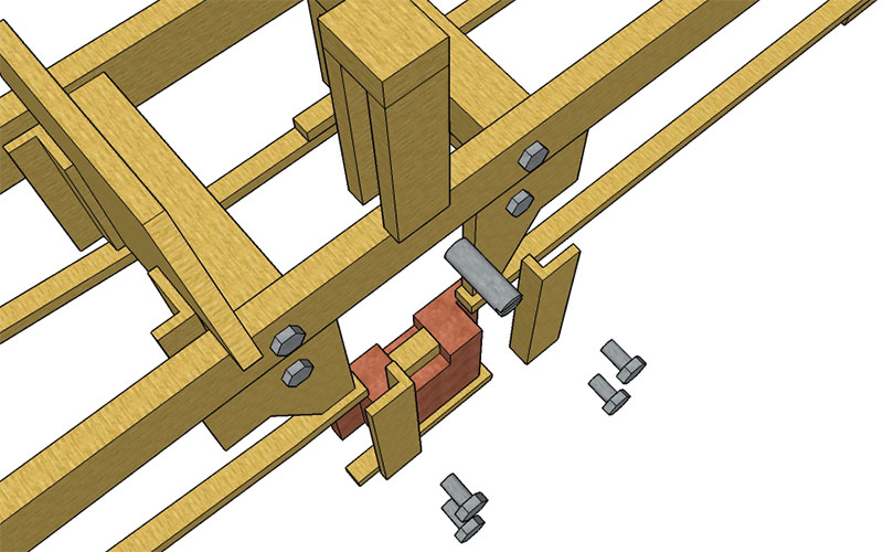 The actual breakthrough on my behalf is more visible in this exploded drawing: The bearing will receive a cut-in in which the connection to the springs will be placed. As mentioned, I want to braze a piece of foursided brass, which will allow me to construct this mounting without a mill. I’m also thinking about securing the spring connection with a threaded rod, although I’ll have to check first whether I can remove that rod without having to disassemble the driver set. I’d like to be able to remove the whole driver set including the bearing as one group from the frame – but I’ll have to wait and see whether this is going to be possible and necessary, too.