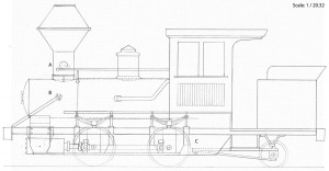
At long last, I managed to finish the drawing and found the time to post here:

I’m quite happy with it as it is. I found one error so far, that is I didn’t align the cylinder’s axis with the drivers’ axes… Right now I really don’t have the nerve to fix that so please consider it as noted on my to do list.
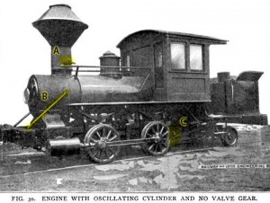
Now, as promised, I’ve got some questions for you guys and hope you can enlighten me. I marked several spots on the Prototype picture:

@A: I’ve got no idea what this is. Looks like an opening to the smoke stack. Maybe a way of disposing of cold sparks which were caught by the spark arrestor? Help me out here, please!
@B: I always thought those were mere handrails, but I’d like to know whether they were also supportive structures. Any comment?
@C: The prototype picture has very little contrast in this area and is too dark, so I’m guesstimating. I can’t imagine a locomotive of this size without any braking system. Since there seems to be no brakes between the drivers, I’d imagine this would be the spot to put some brakes on the rear driver, probably a non-powered type. What are your opinions?
As always, I look forward to any kind of feedback, criticize away, make observations, sound your opinions. Thanks in advance!
The next step is to switch techniques. Until now, I felt safer drawing on paper, somehow I was bolder in filling uninterpretable areas in the photography with my own ideas while I used a pencil. Now I’m more confident and I want to do a 3D-model on the computer. There are several advantages, like seeing how parts actually fit together, adding dimensions to any part or parts of the whole machine, creating prints from any perspective in any layer, and so on.
