Hello there,

it’s 8 am, thunderstorms are rolling in after a week of intense heat (thermometer topped at 110 °F) and I can finally spare some minutes to keep you updated.
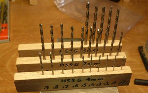
Last week I ordered a whole set of small drills, so far I had a very limited stock. Now my options are quite unlimited when it comes to making threads and clearance holes. I spent some time in the shop building a neat set of holders.
Those are going to stay near the drill press and will eventually move in my tool cabinet (I guess sometime in the 2050s, when I’ll finally have enough money, space and time to afford a dedicated workshop…)

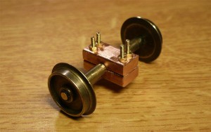
Along with the drills came the first batch of construction materials. Based on my SketchUp plans I ordered some brass, threaded rods, screws, washers, nuts, … the like. Since noone objected to my idea from the last post and a good friend of mine encouraged me as well, I got a fine copper bar with the right dimensions and constructed the bearing for the trailing wheel set.
So far I’m very happy with the result. The axle runs freely, I can barely feel any friction and although I filed the axle down manually (see above post) there is neither misalignment nor friction caused – looks like I actually managed to pull of a clean result.
Nevertheless I’m quite sure that I will redo the bearing pieces eventually. I think an even tighter clearance would add stability to the locomotive’s movements, but of course I won’t decide that until I actually have the frame on the tracks.
Now, some questions for you guys: The bearing is going to be attached to a boom linked to the frame below the cabin. The photo that I have from the prototype doesn’t provide useful information but I imagine the trailing wheel directly supported the tender. What do you think about that? Do you have any other images of trailing wheels supporting the frame? Or were they only guiding the drivers in tight curves?
And on top of that: If the trailing wheel did support the tender, I think there should have been some sort of suspension. Do you have any references or suggestions how such a suspension would have worked and looked like?
As always I thank you in advance for your feedback.
