
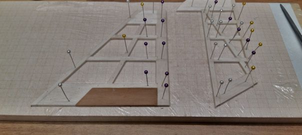
The structural work is coming to and end: since the horizontal stabilizer has made much progress, it’s the vertical stabilizer’s turn.
Horizontal stabilizer and elevator reinforced.Even while building the horizontal stabilizer I realized I made a design error: the thin leading and trailing struts have been glued to the tips as butt joints, lacking adhesion area and thus stability. I rectify this by reinforcing the corners with small wedges of balsa wood. And this enlightment directly flows into the vertical stabilizer.
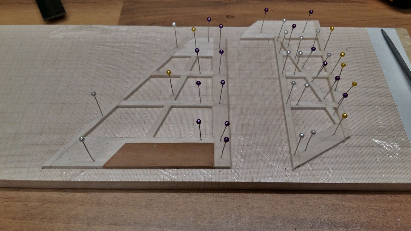
As one can see, this time the trailing edge runs the whole length of the stabilizer. Again, the tip is going to be sanded from a solid piece, but this time it’s glued to the back of the leading edge. I presume this to add significantly to the design’s stability.
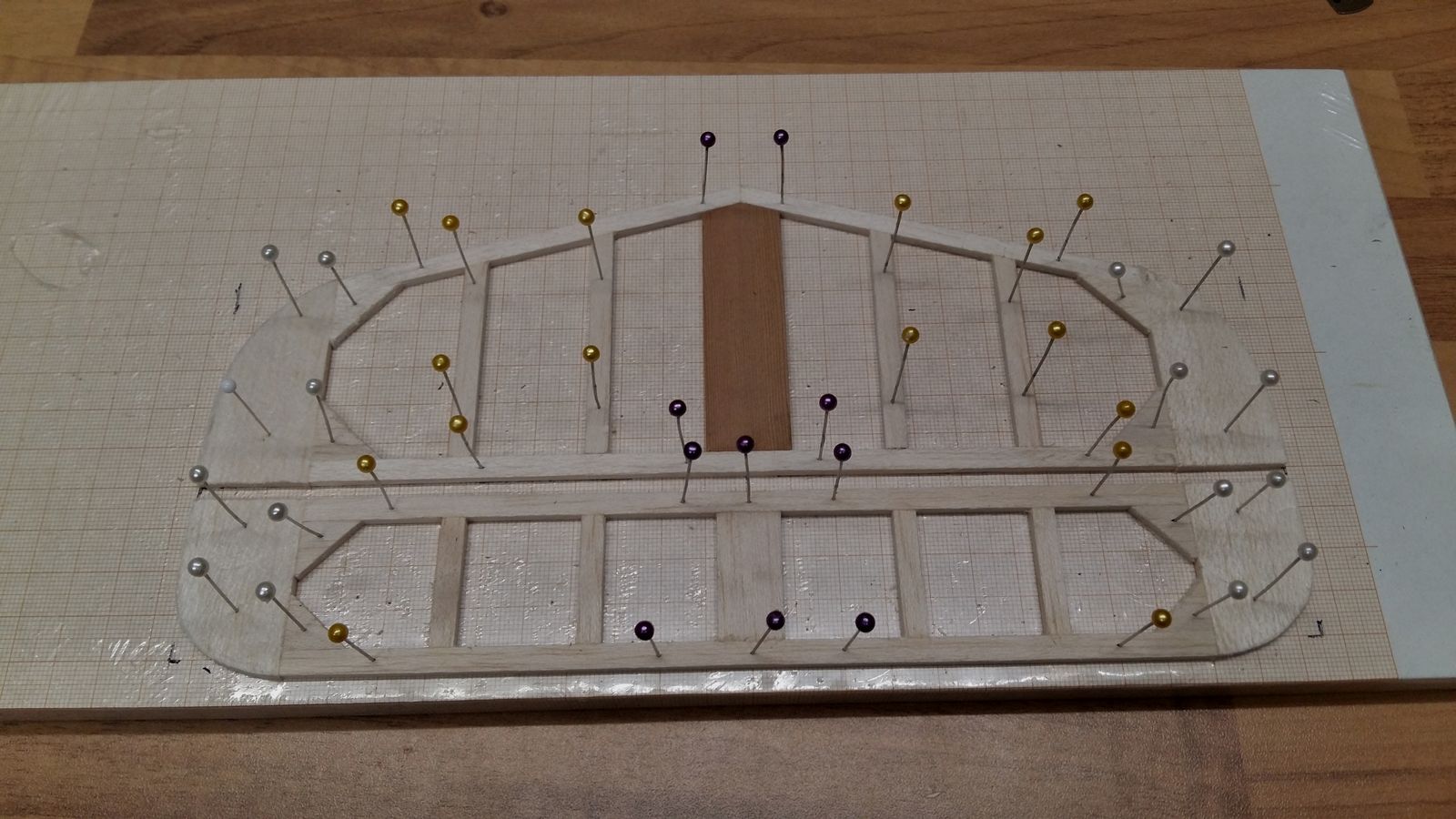
The vertical stabilizer is going to be screwed to the fuselage, clamping the horizontal stabilizer in the process. If the screws are supposed to hold tight, they have to have some solid wood to bite into. Because of that I’ve spliced the stabilizer’s basis with a piece of red cedar. I’ve never mixed different types of wood that way and I’m quite anxious to find out how well it will cope. However, I’m optimistic.
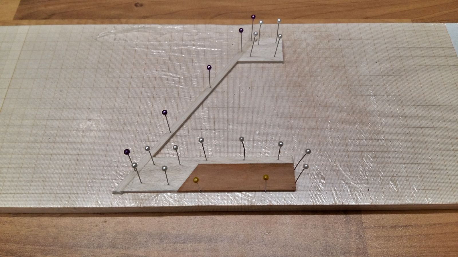
In order to improve the rotational stiffness, I add a traverse strut to the vertical stabilizer and rudder each. Since my elevator will be placed immediately below the rudder, I’ve constructed its base with a 30° angle. At this point I realized that I’d have to chamfer either the rudder’s leading strut or the stabilizer’s trailing strut.
And it went profoundly awry.

This blunder happened because I started constructing without thinking it through to the end. Chamfering a strut with a circular saw is very easy, as long as one can use the rip fence. However, I completed the vertical stabilizer before thinking about this step. Trying to place the stabilizer on the transverse stop ended with quite a mess.
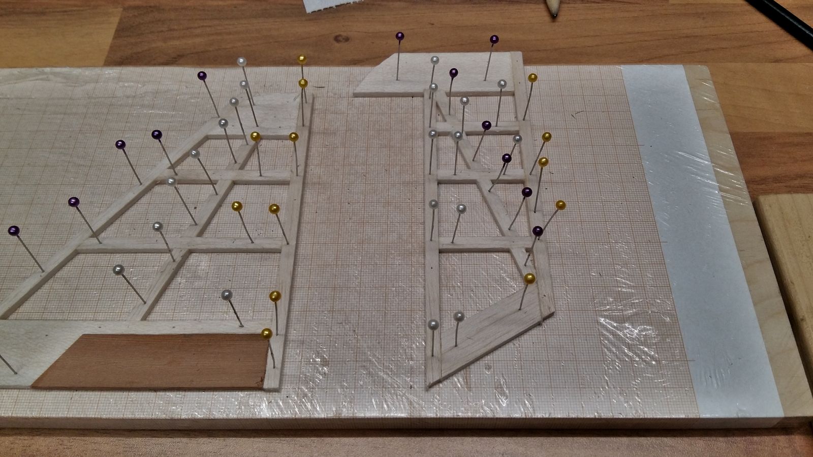
Here the scratch-building shines, as does the circular saw: One simply cuts off the messed-up part and starts anew.
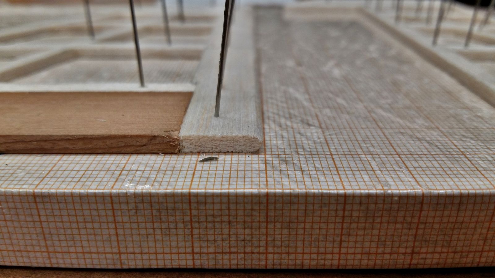
The strut was chamfered from both sides to an angle of 30°, in order to allow for according rudder deflections. I took advantage of the opportunity to file grooves for the transverse slats.
As one can see, I chose a broader slat for the trailing strut. I just wasn’t comfortable with a single slat of 5mm by 3mm to receive the high loads of the rudder.
Next time, the tail plane is going to be assembled.