
Finishing the vertical stabilizer only leaves the tailplane’s assembly. Here, three important objectives have to be met: the horizontal stabilizer must be in parallel to the long axis, so must the vertical stabilizer, and the vertical stabilizer has to be at right angles to the horizontal stabilizer.
The most important contribution to the right angles is provided by clean, perpendicular cuts, which I can achieve easily thanks to my table saw. In order to further stabilize this orientation, I’ve constructed two guides from balsa wood and sanded them into a streamlined shape.
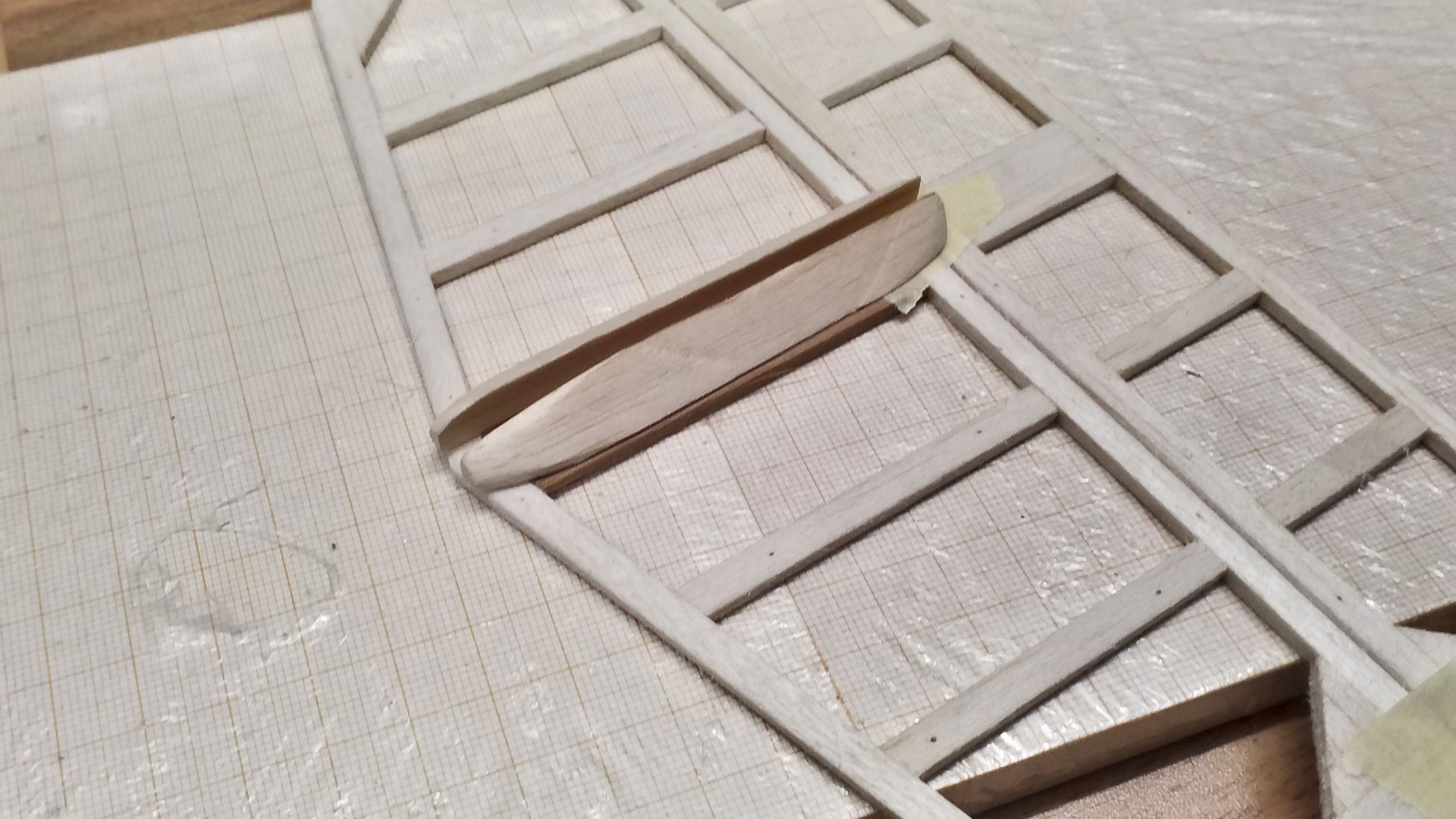
At the same time, these guides are supposed to align the vertical stabilizer in parallel to the aircraft’s long axis. A first assembly rehearsal looks promising.
On the other hand, this tasks the horizontal stabilizer with the alignment of the vertical stabilizer. So, the horizontal stabilizer not only has to be in parallel to the aircraft’s long axis, it also needs a force-fit link to the fuselage, so that it can’t twist along the yaw axis. To that end, additional pieces of balsa wood are glued to the fuselage, which are supposed to force the horizontal stabilizer’s alignment.
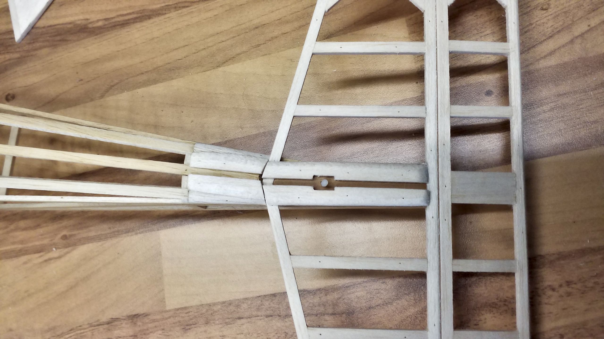
Below those, the tailplane’s mounting is glued in place, again made from red cedar. The hole accepts a nylon screw of 3 mm diametre.
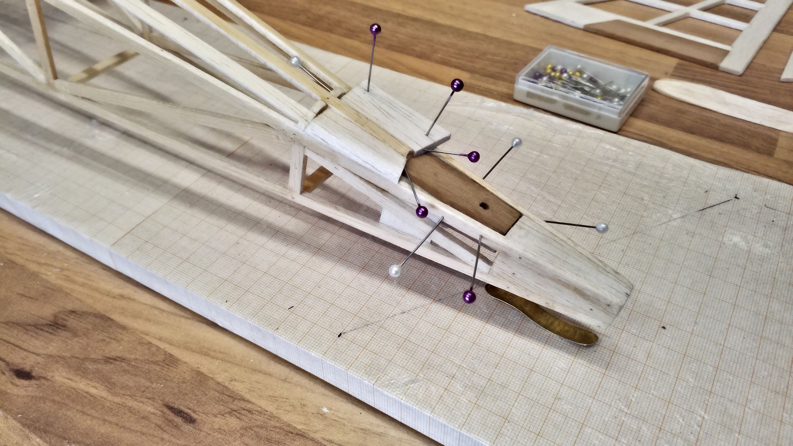
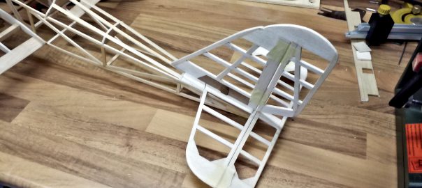
This is how the finished mounting and horizontal stabilizer’s guide look like:
Of course, the vertical stabilizer needs a threaded hole for the nylon screw, so it can fix the horizontal stabilizer in place. Since the tailplane is entirely made from slats 3 mm wide, some reinforcements had to be glued to the vertical stabilizer.
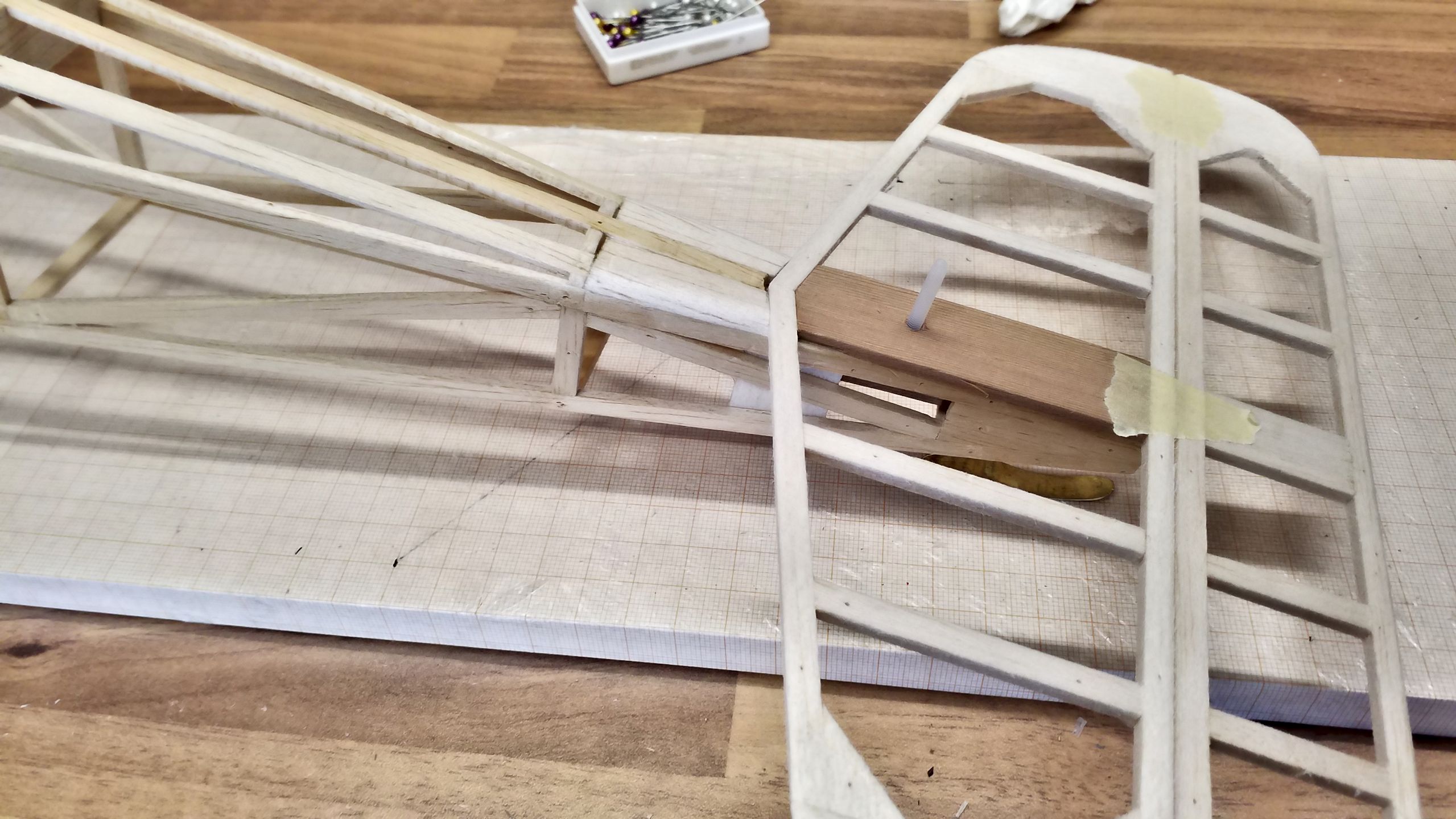
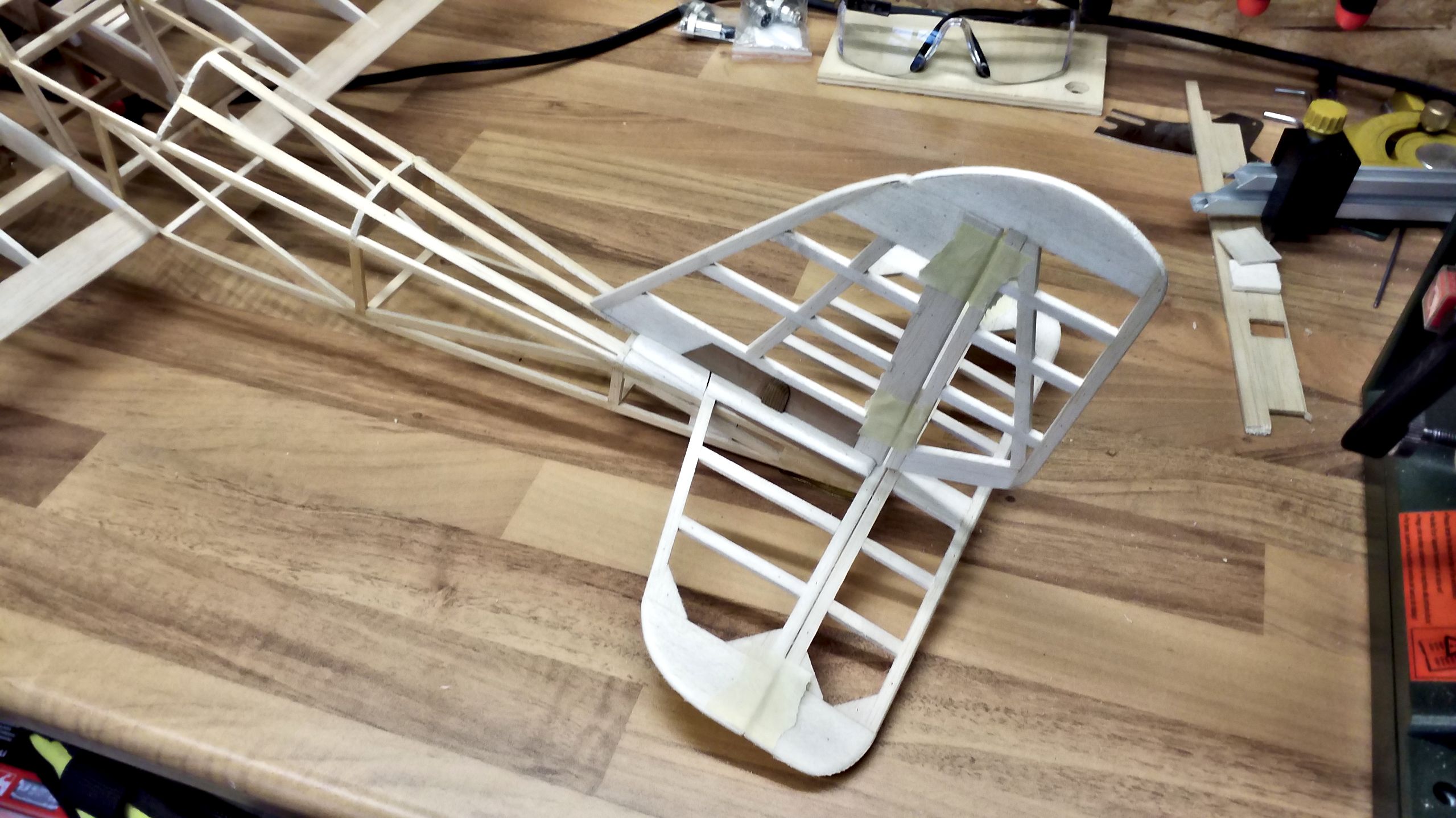
Some tests of the whole contraption revealed a design error: the horizontal stabilizer’s guide only has got an extremely short lever, specifically the fuselage’s width just shy of 3 cm at the level of the horizontal stabilizer’s leading edge. This has to counter the forces applied by the whole vertical stabilizer’s length. If one looks at the picture above, the unfavourable lever proportions are quite obvious. What to do?
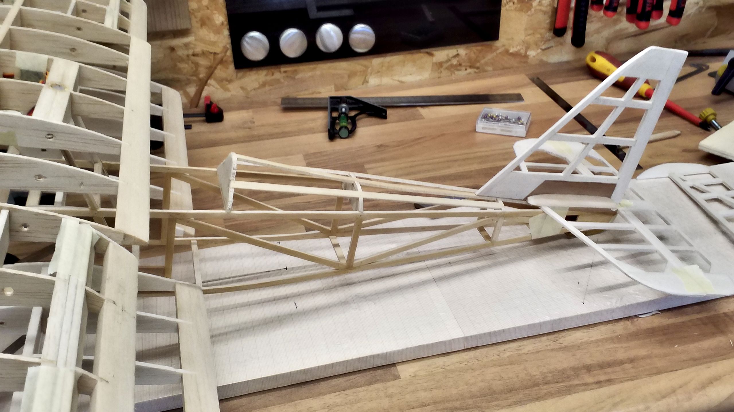
The simplet solutions often are the best: flip the concept. The longest distance to the nylon screw is found at the leading edge of the vertical stabilizer, so that’s where the stabilizer has to be locked in place.
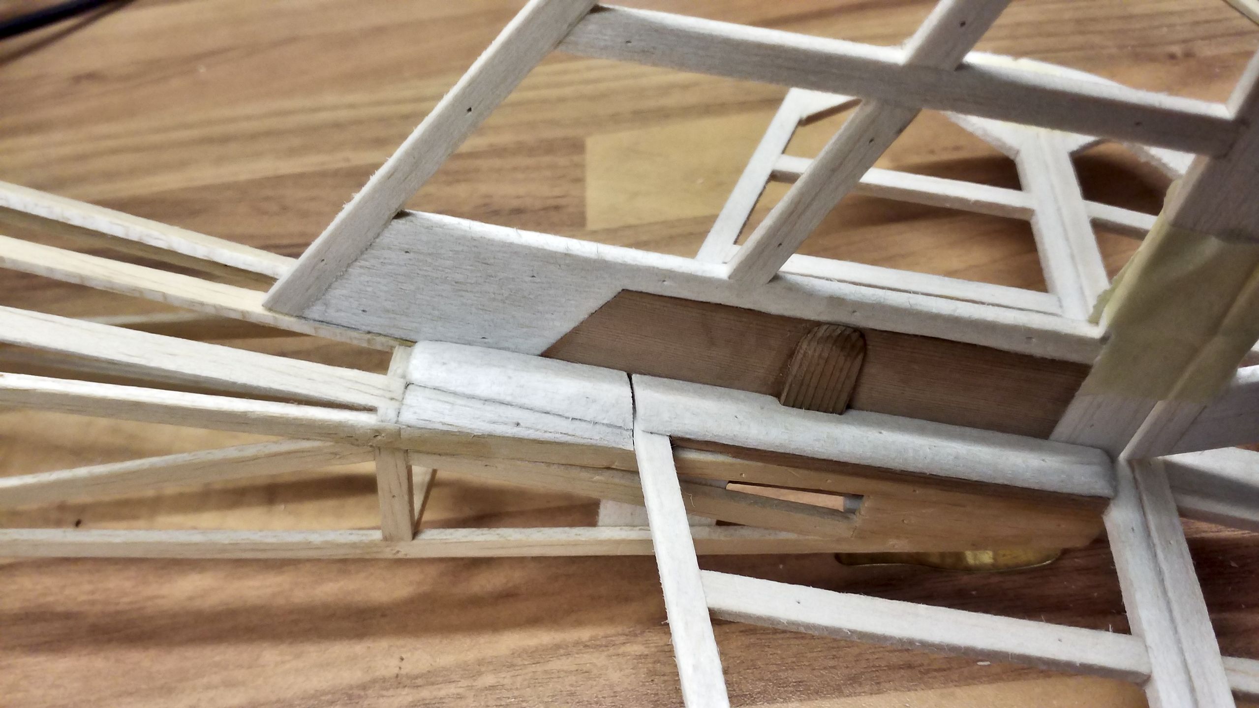
This locking guide will keep the vertical stabilizer in parallel to the fuselage and prevent it from twisting around its yaw axis. This guide is continued by glueing slats on top of the horizontal stabilizer. In fact I constructed two long slats first, then sanded them into a streamlined shape and in the end cut them to length, so that I’ve got a forward and rearward pair of guides.
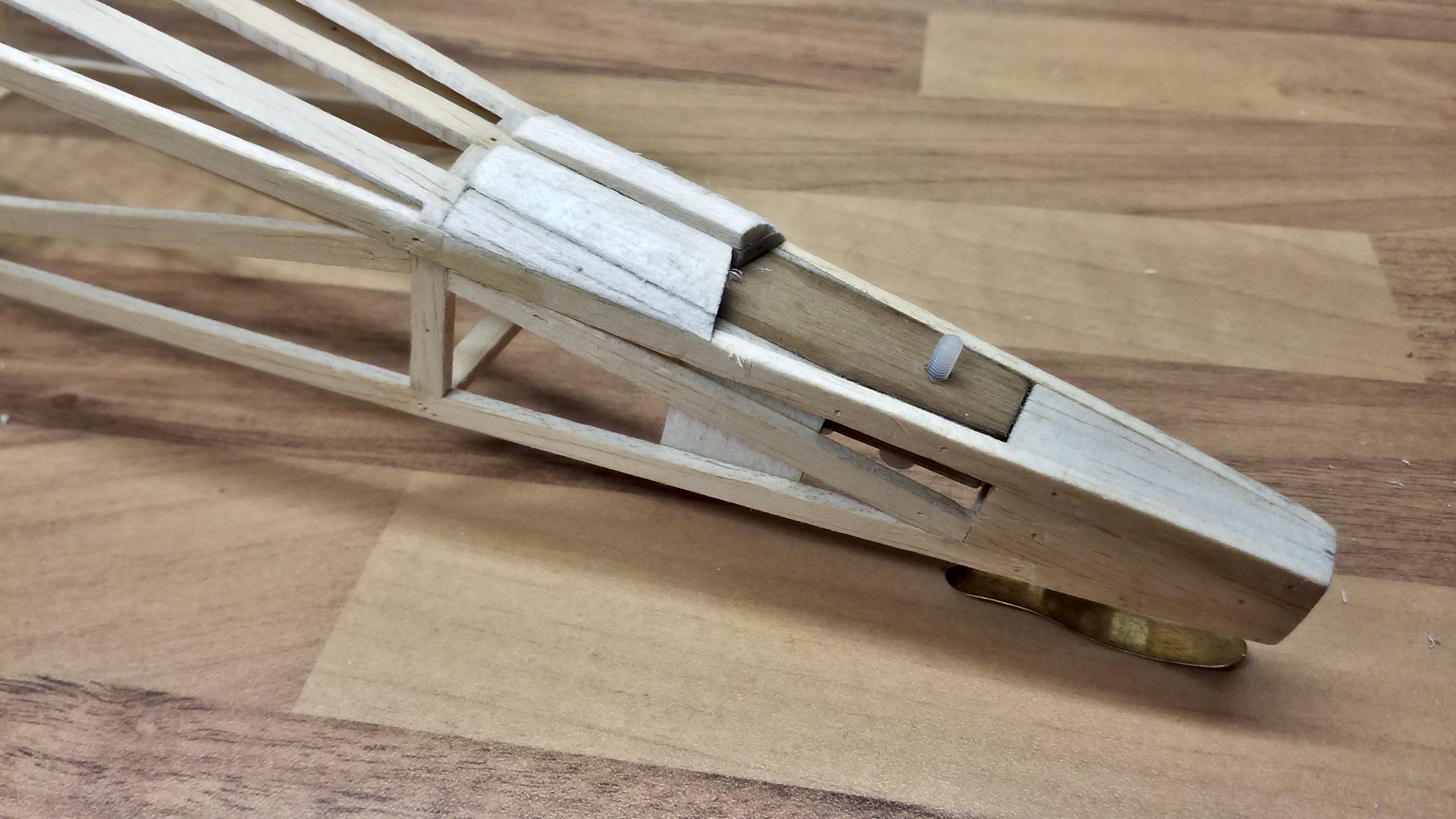
As can be seen, any twisting of the horizontal stabilizer is blocked by the sturdy vertical stabilizer’s base. The nylon screw keeps everything in place and by compressing the parts the construction is addiontally stiffened.
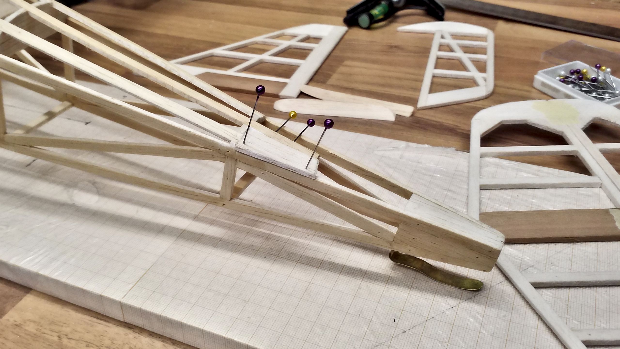
And this is how the whole, assembled tailplane, complete with provisionally fixed elevators and rudder looks like:
This concludes the construction of the framing. To me it’s quite a remarkable milestone and reason to celebrate.
From now on, the model is going to be outfitted. And it will commence with the power train.