

Based on the design variations, I’m moving on to the actual planning and start to blueprint the nose. If possible, it is supposed to give the aircraft a semiscale appearance and that means I basically have to start from scratch.
In order to create parts repetitively and precisely, the blueprinting is going to be computer-assisted. In theory I could draw on paper, scan the diagrams and print them. However, I would lack the 3D preview and applying adjustments is going to be much more time-consuming.
The greatest obstacle to me is to get a grip on FreeCAD. What’s a “degree of freedom” again?! It takes several hours and as many tutorials until I understand the basic principles and the most important workbenches. And as a first sample for my new skills, I tackle frame No. 6 from the original drawings. It connects the nose with the rest of the fuselage.

Since it’s shaping up well, I make some adjustments for my semiscale nose immediately. I don’t want to use balsa chamfer strips which are sanded into a round shape. Instead I have a curved planking in mind, supported by stringers.
On these adjustments I have to spend another whole evening, but they pay off. From here on, I can insert some basic stringer drafts into my model. Frame No. 5 follows up swiftly, again with some adjustments for the rounder shape.
However, the design stays somewhat box-shaped. This calls for a switch in strategy: Instead of adjusting the original fuselage’s rectangular frames, I’m testing the ellipse tool for frame No. 4. This costs me yet another whole evening, until I know all the wrinkles of constraining ellipses.
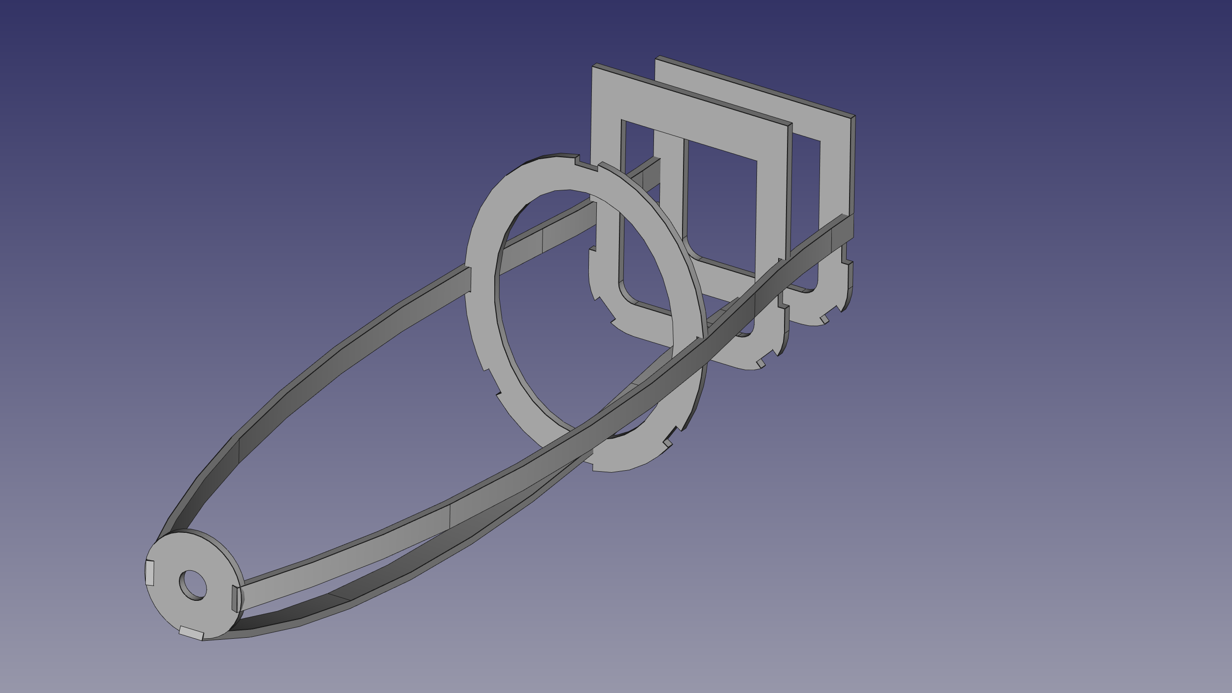
At any rate, the result seems to work. So from now on, I’m turning away from finishing single frames in a precise manner because that is to make the third or fourth step before the first. After I know that I can draw a frame completely, I roughly draft the nose’s whole length.
Naturally, my hand-drawn stringers don’t fit anymore in any way for these ellipsoid frames, so I’m using the ellipse tool in order to hint an outline for the nose’s shape.
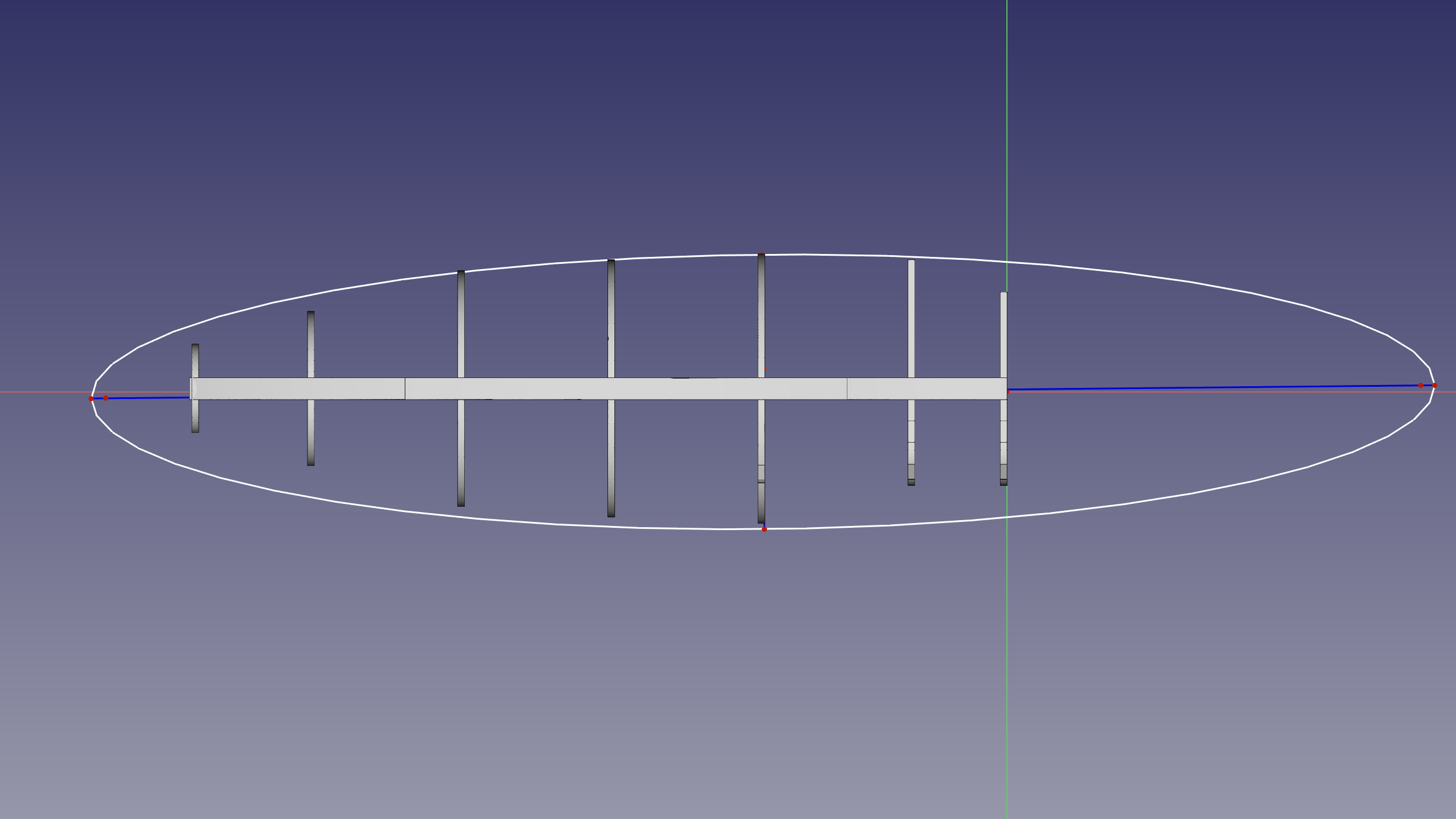
This ellipse is trimmed down to a cut-off, which gives me a good template to place the apices.
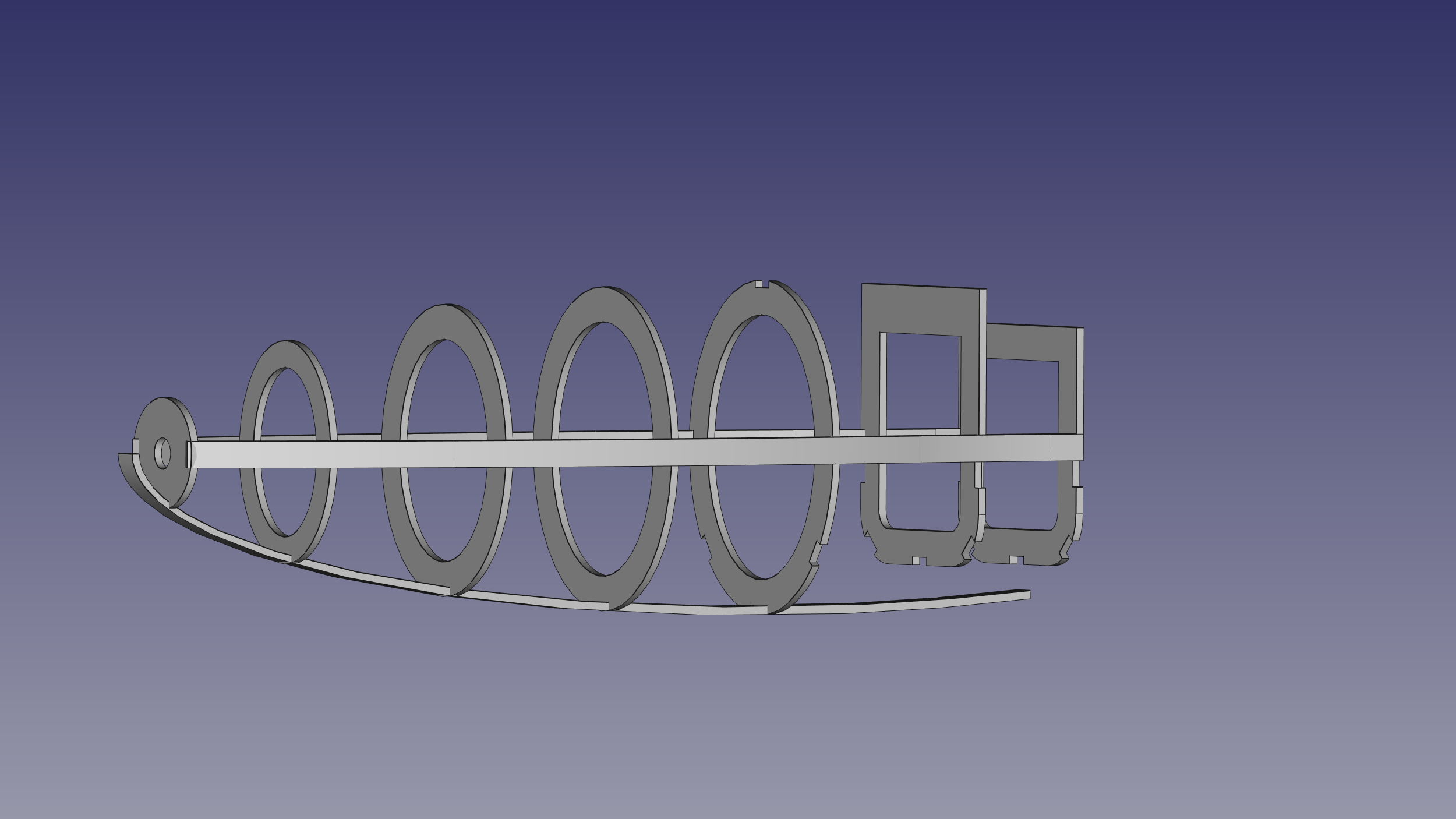
As one can see, the nose’s new belly is quite a bit lower than the original one. So, next up, the belly stringer has to curve upwards in order to connect to the fuselage. After that, I will redraw the original frames 5 and 6 with an ellipsoid shape in order to adapt them to the nose. Thus I move alongside the nose forward and backward, while converging on my envisioned design.
Next time, the fuselage is up.