
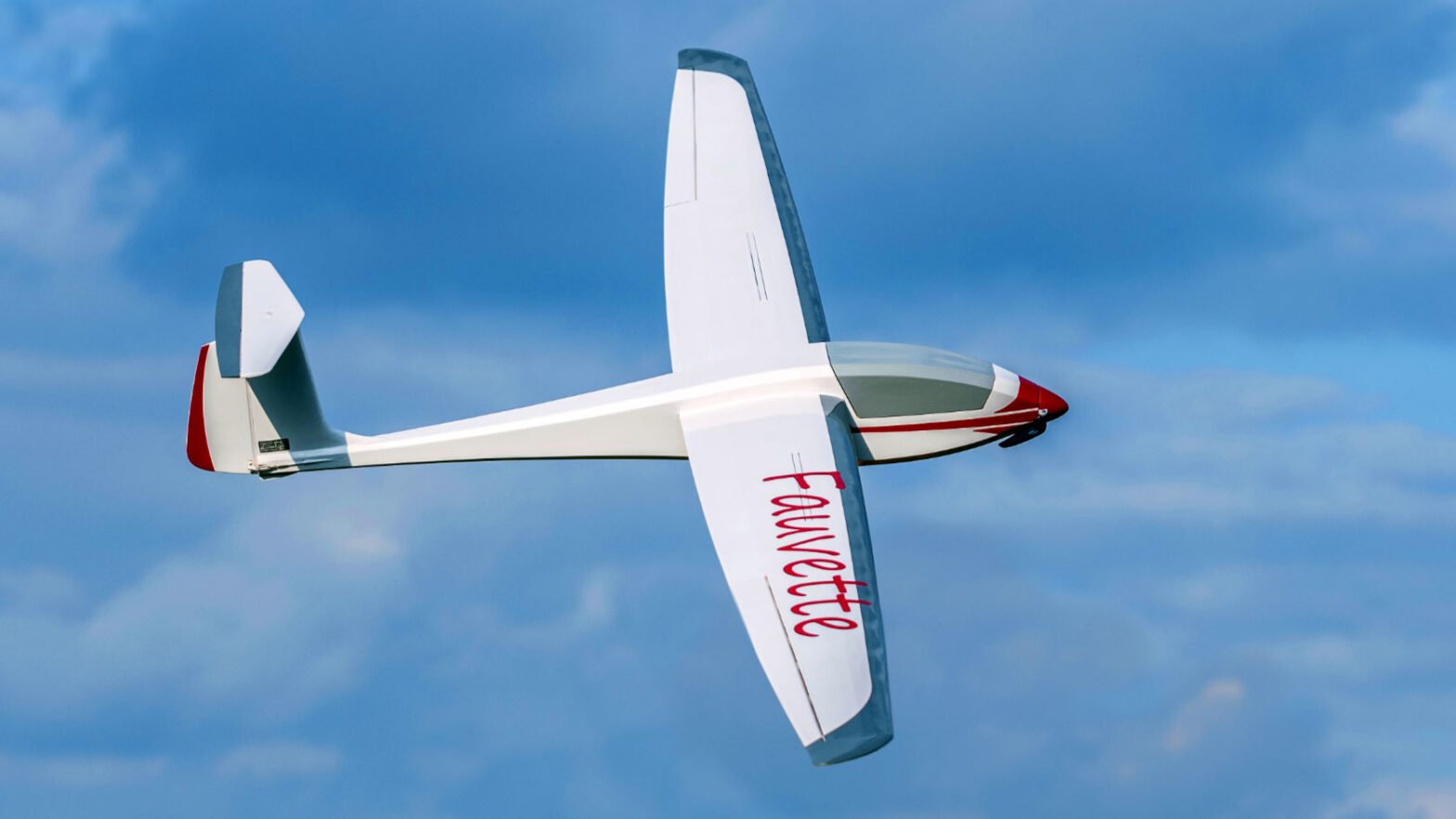
Since I reengaged into model flying, I’ve been looking forward to a bigger glider. And all the while, I wanted to build from scratch. The Joyrider was a first test for myself: Would I have the skills and patience to build an aeroplane?
There were several ideas and attempts to build such a glider, but they failed for various reasons. But then, I was lucky to meet Hilmar Lange from Münster who was kind enough to demonstrate his Fauvette. My enthusiasm was huge, the diagrams were printed fast and then… life took over. However, in winter 2024 enough time and motivation were available and now Fauvette is under construction.
Hilmar has really put a lot of time, love and effort into the diagrams, not only do they contain cut-out templates for all required parts, there are also illustrated instructions which accompany the building process. On top of that he’s released a 3D-model of the model on his website, so one can watch at the model from any imaginable perspective to clear out any uncertainties. Chapeau, Hilmar, my utmost respect for this commitment!
First order of business was to saw out the formers from poplar plywood. Since I need to build on a budget, I chose rather cheap material from the hardware store. That means sorting through B or C grade, or to put it bluntly: some boards are unusable because they’re warped or bent and the rest of them has knots, which can’t be part of the model – those would be destined to become breaking points.
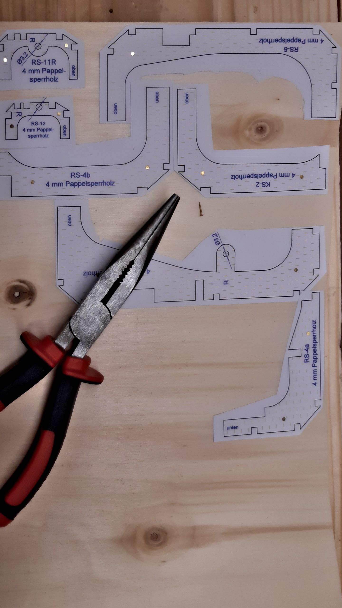
The above picture shows how to avoid these knots while placing the templates. The latter are glued to the board with a weak glue stick. The pins are not used to keep the templates in place, but the second board which is placed beneath the visible one. For Hilmar has designed the fuselage to be built in two halves. It makes the building process much easier because no jigs are needed to keep the formers aligned, however one needs absolutely symmetrical parts. Those are built best by cutting them at the same time. The pins keep the two parts together so they can’t shift against each other.
After a few hours at the band saw, all formers were sawn out. After that, I used my circular saw to rip the stringers from a pine board. That turned out to be far more difficult than I had imagined, since pine has a nasty habit of releasing tension while being ripped. Thus, the stringers are one tenth of a millimetre thicker or thinner here or there. I will give it a go nonetheless and I’ll probably pay for that with a lot of sanding. But still, I’d like to try.
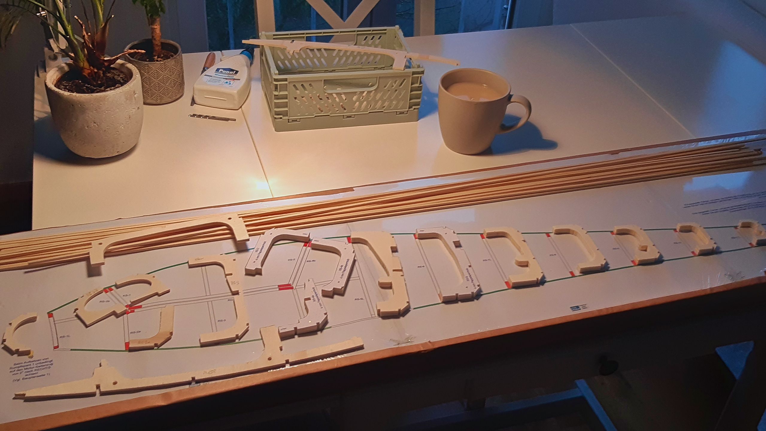
The fuselage’s blueprints need to be assembled from three DIN A3 pages. They are supposed to be glued to a particle board which in turn is to be covered in clear adhesive film. However, I decided to use one of the building boards which I built for the Thermy. The diagram is pinned to the cork and covered in film which is fixed to the board’s rim with duct tape.
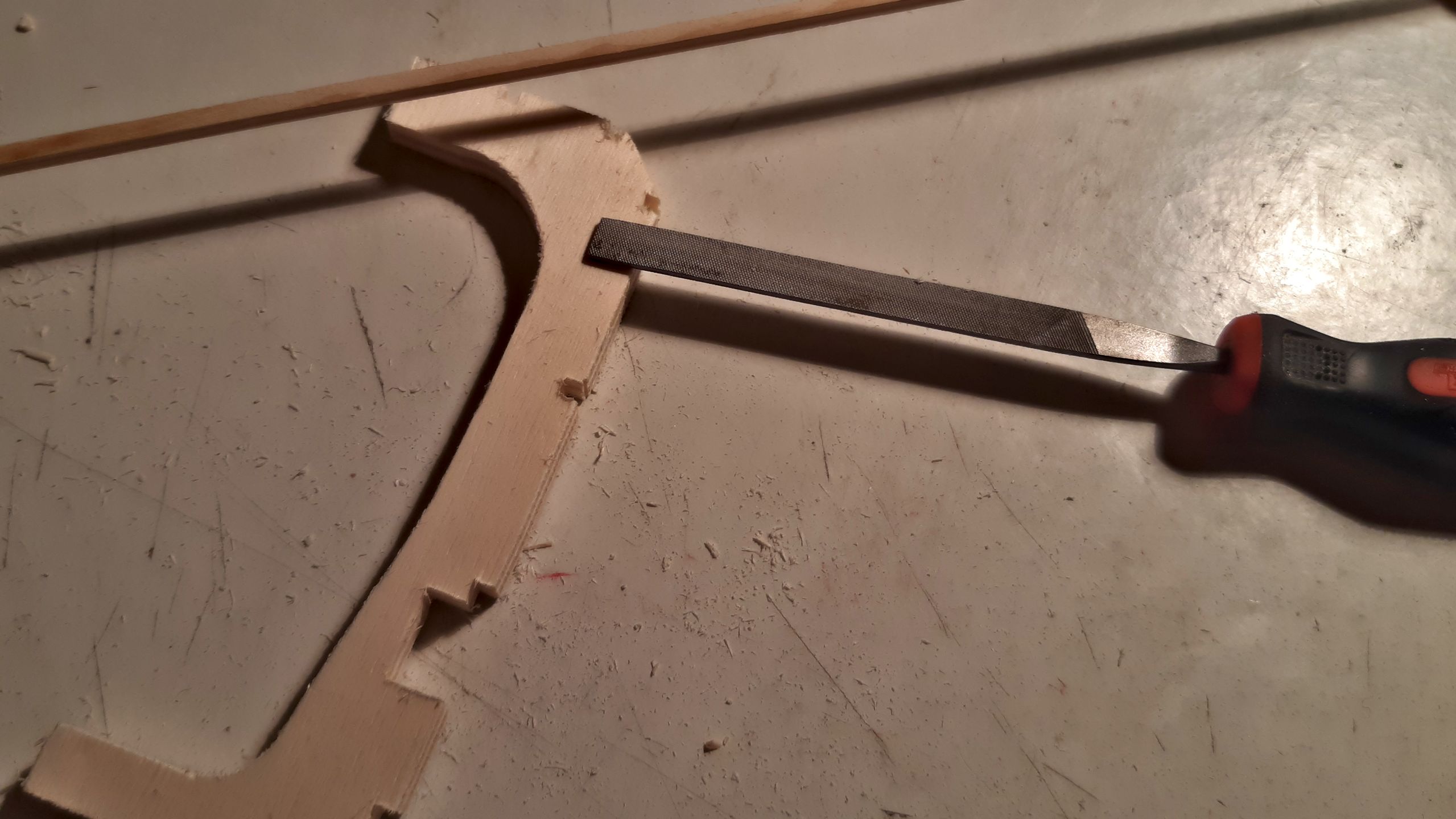
The cut-out parts are first separated, and the sawn edges are sanded. Next, the rough-cut slots for the stringers must be filed to the correct size so that the formers are not subjected to excessive stress after being set up on the building board.
The formers are first positioned on the plans using wood glue and held upright with small blocks. This joint is relatively loose, but it holds well enough to connect the formers to the stringers.
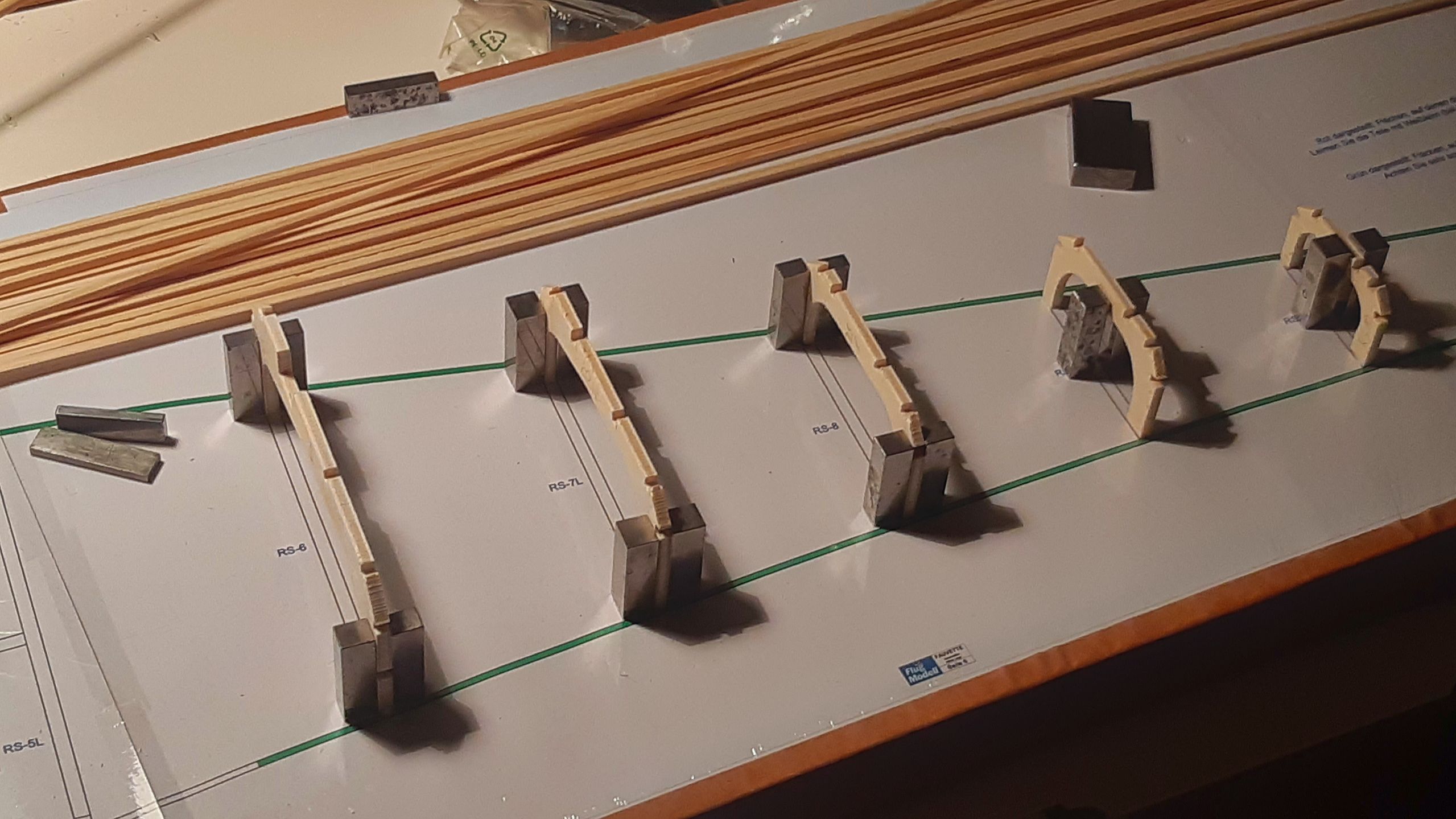
In the nose section, the formers for the fuselage and the canopy are glued together. A gap must be left between the canopy and the fuselage so that the canopy can later be cut free using a saw blade. The trickiest areas are the side thrust angle of the motor mount former and the “floating” former 5, where the landing gear is to be installed later.

Next time, the stringers are up.