
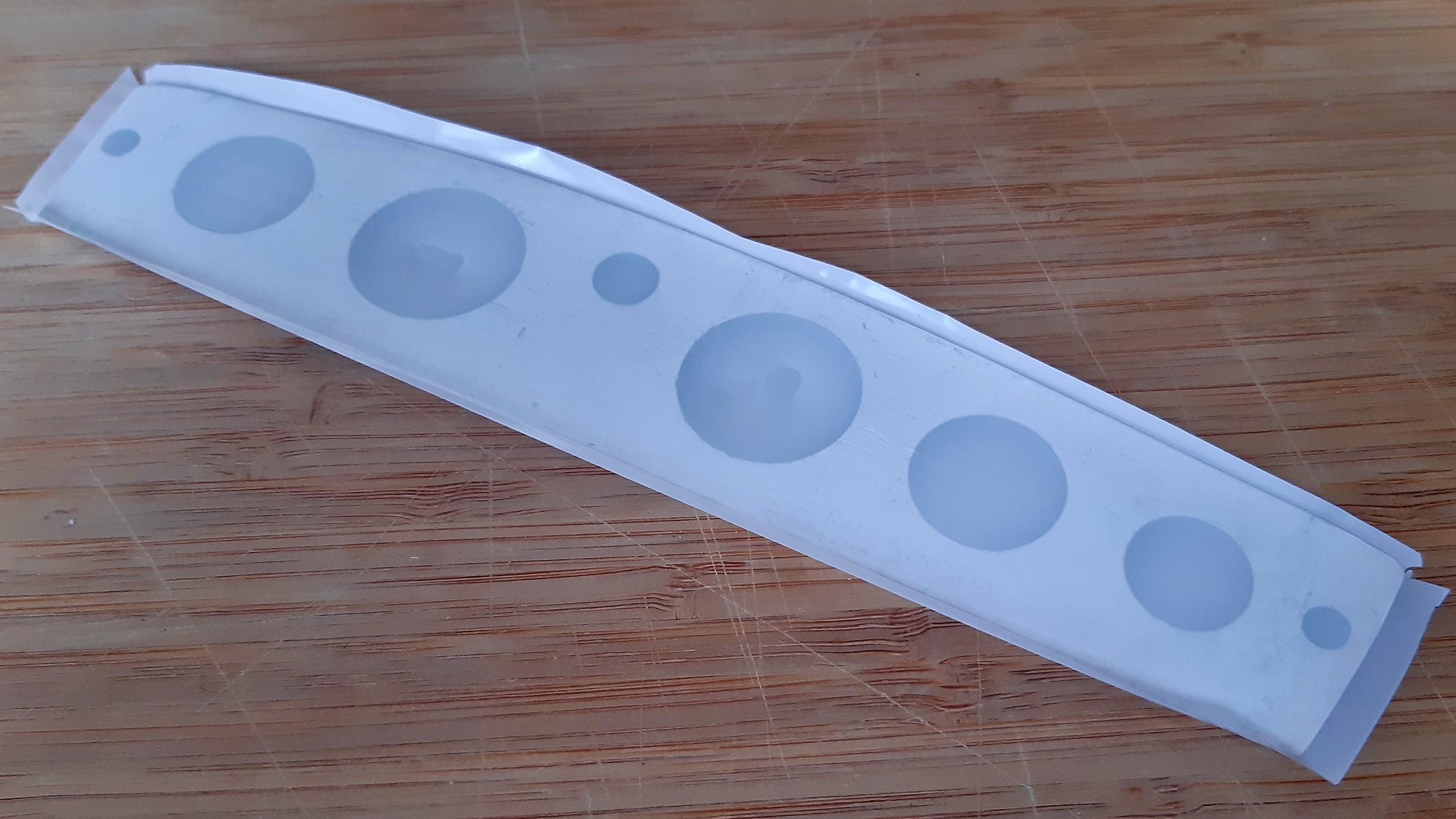
With the finished priming the covering can commence. I like to use Oracover because it’s really easy to work with and yields very good results. I always start with the easiest parts in order to get re-used to the task. So first up is the rudder.
…and one can easily spot that I managed to fuse the foil in the recesses. In this case I was lucky and could get them apart with some additional heat, but often enough one has to start over. With due warning received, the ailerons come up next. On the left side of the pictures some creases are still visible, which will disappear in the last step which is heating up the whole area.

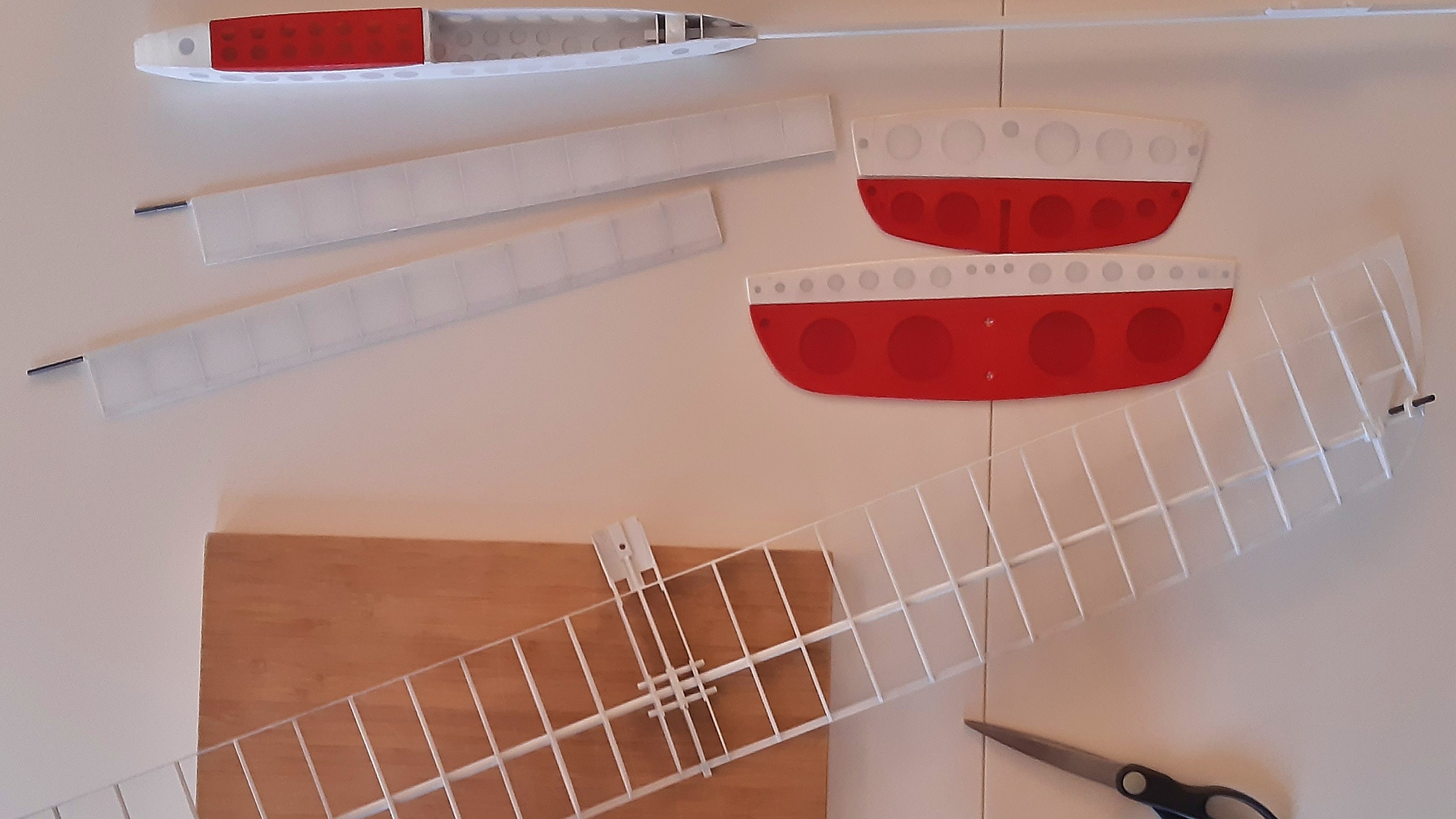
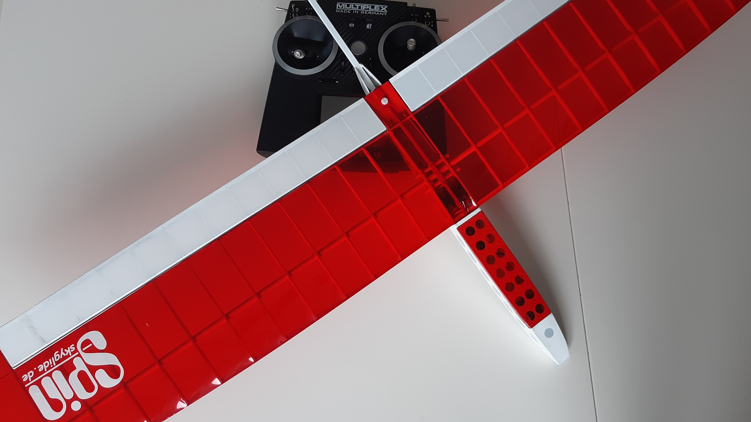
In relatively short time i covered all parts, except for the wings which need special attention. As one can see, I chose transparent red and white foil in order to showcase the light construction of the airframe. The photo also enhances how the black carbon fibre launch pin stands out from the primed wing.
Covering the wing is swiftly finished and I’m already quite pleased with myself… until I’m test-fitting the ailerons and notice that the starbord aileron is jammed by the wingtip. The shrinking foil has excerted so much force that the wingtip is bent inwards.
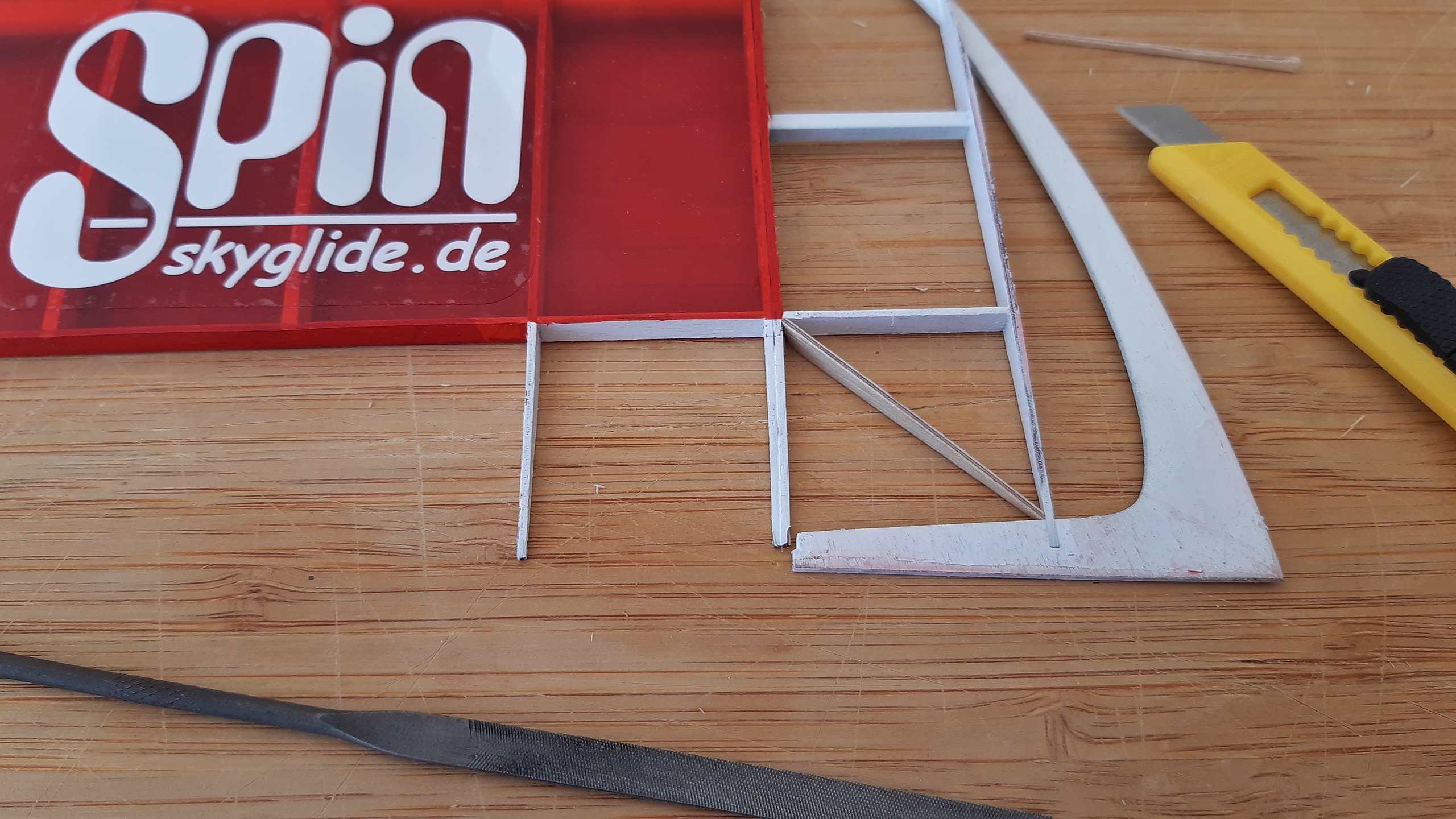
Vexing, but no disaster. First off, the wingtip is stripped from the covering down to the rib and an additional frame is cut from scrap plywood. It’s supposed to prevent the wingtip from bending inwards. That’s easy to achieve if one cuts a too long piece and then creep up on shortening it until the last rib is straight again.
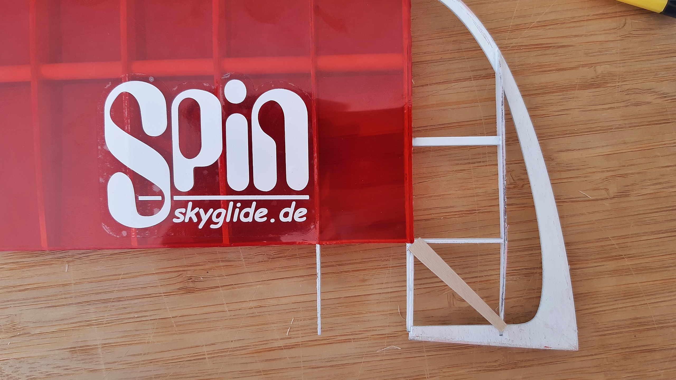
Only then the correct height is marked at both ends and the wing profile’s shape is matched. Sanding frame down to profile is easy when one places a piece of sandpaper flat on the worktop.
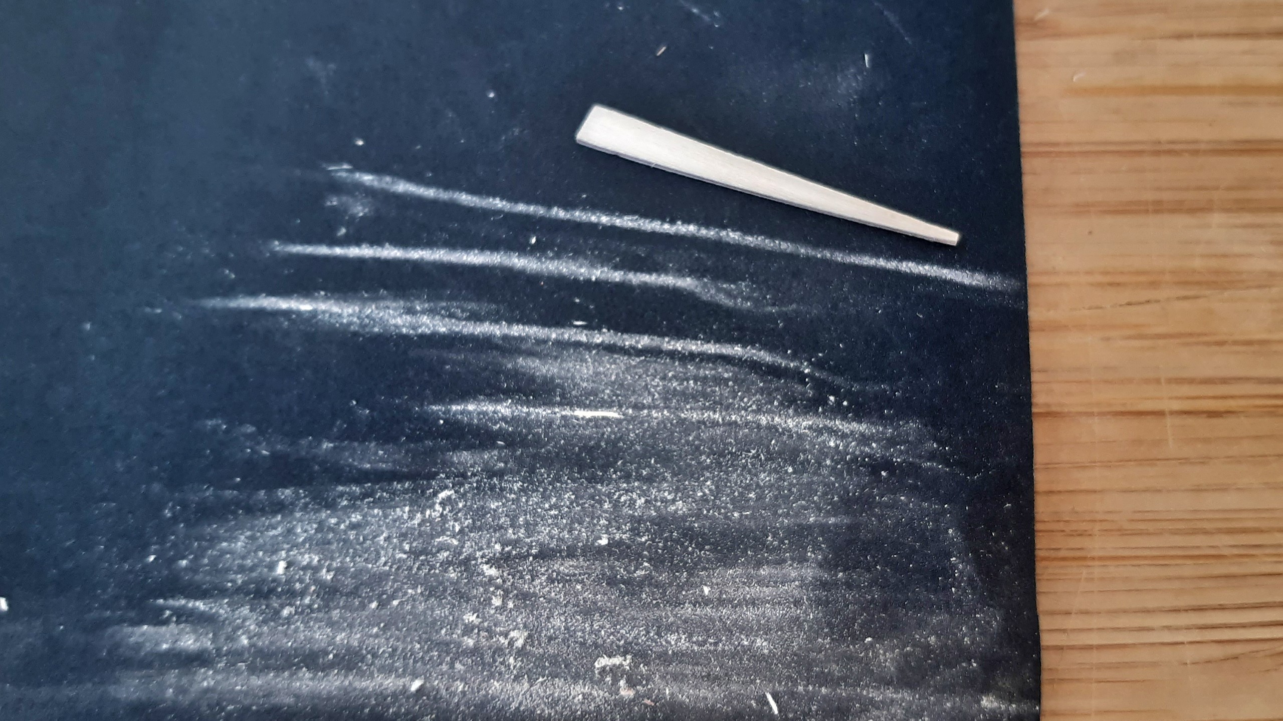
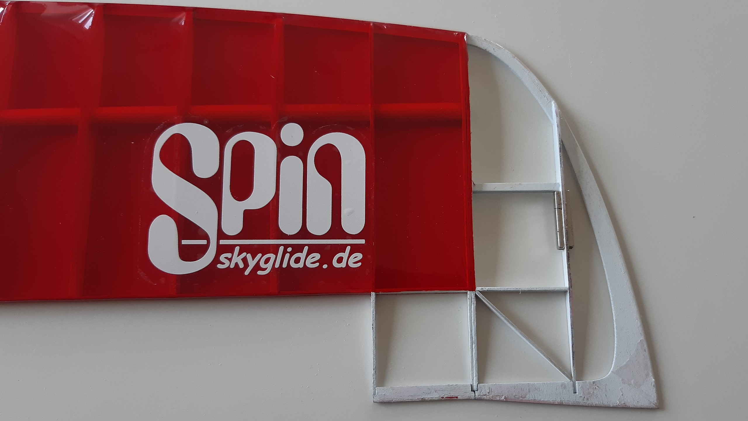
Not even a quarter of an hour is needed and the frame fits into its place. As one can see, there’s just a millimetre of a gap, but that’s the downside of such a precision kit: no tolerance for error.
As soon as the frame is chamfered and primed, it can get glued into place and the remaining parts can return to their places. While I’m at it, I also glued two trim weights to the outermost rib since the left wing was hanging down – although I haven’t got the foggiest on where the weight came from. Perhaps some unevenly spread primer? I honestly can’t tell, but it doesn’t make a difference.
While I’m balancing the wings, I notice an imperfection in the V-shape which is easily fixed with some layers of clear duct tape which guarantee a symmetric V-shape.

The horizontal stabilizer’s mount need some attention, too because the tailplane isn’t parallel to the wings. This is adjusted with some very slight, carefull sanding.
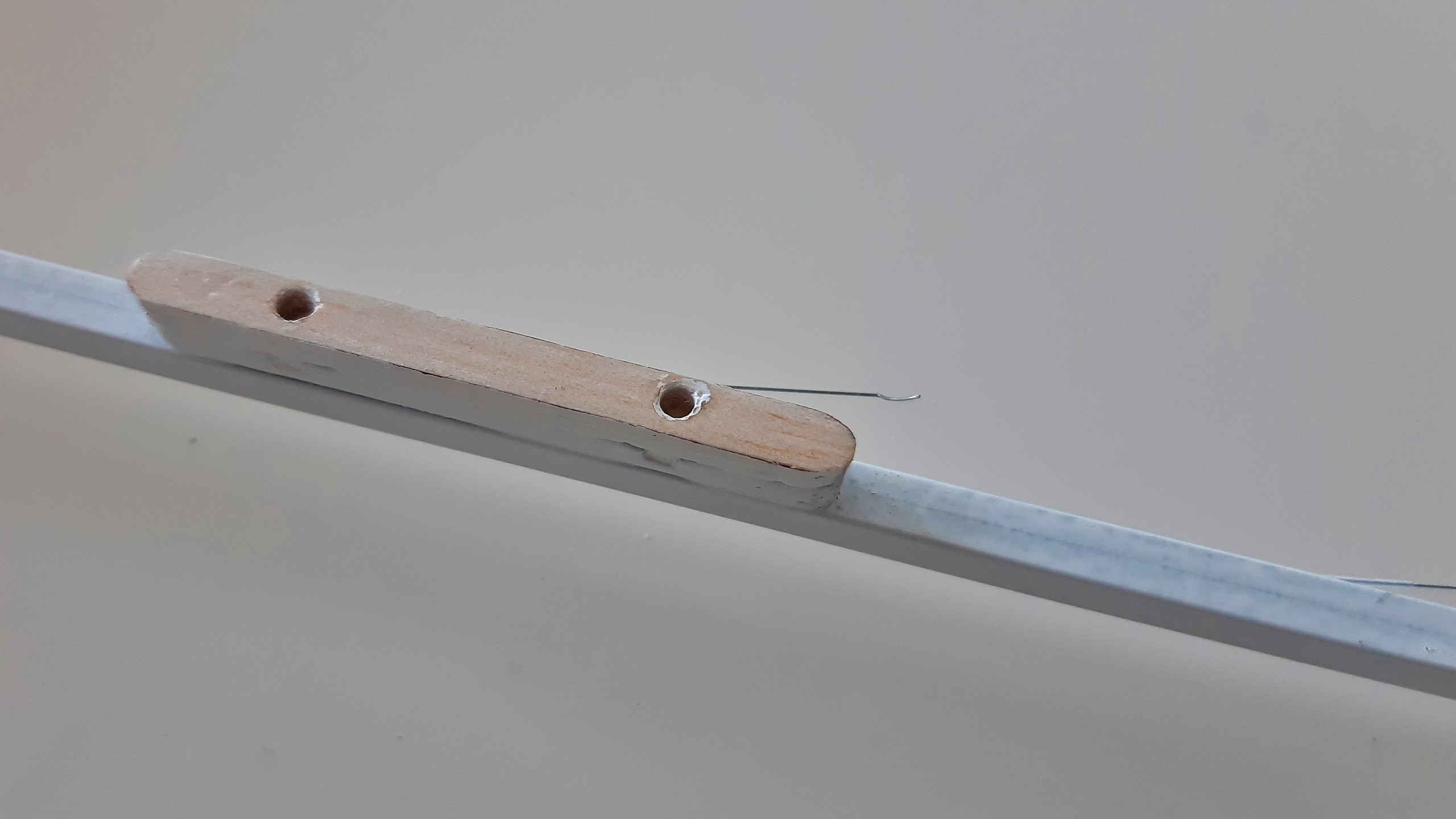
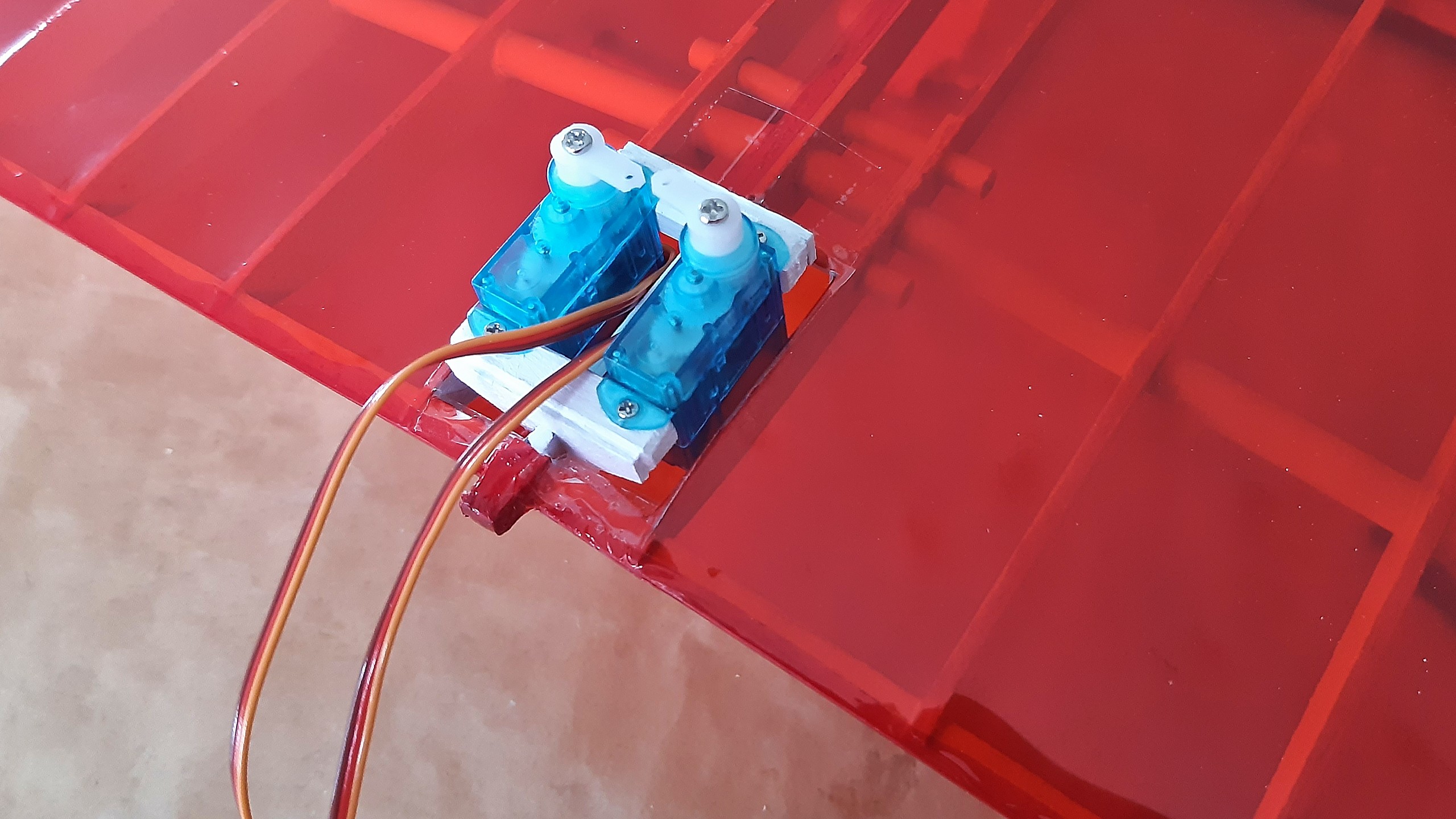
Once these tasks are done and the wing is completely covered, the servos can be fitted. The aileron servos are mounted to the wing with some small wooden blocks. From there the ailerons are linked with short steel rods.
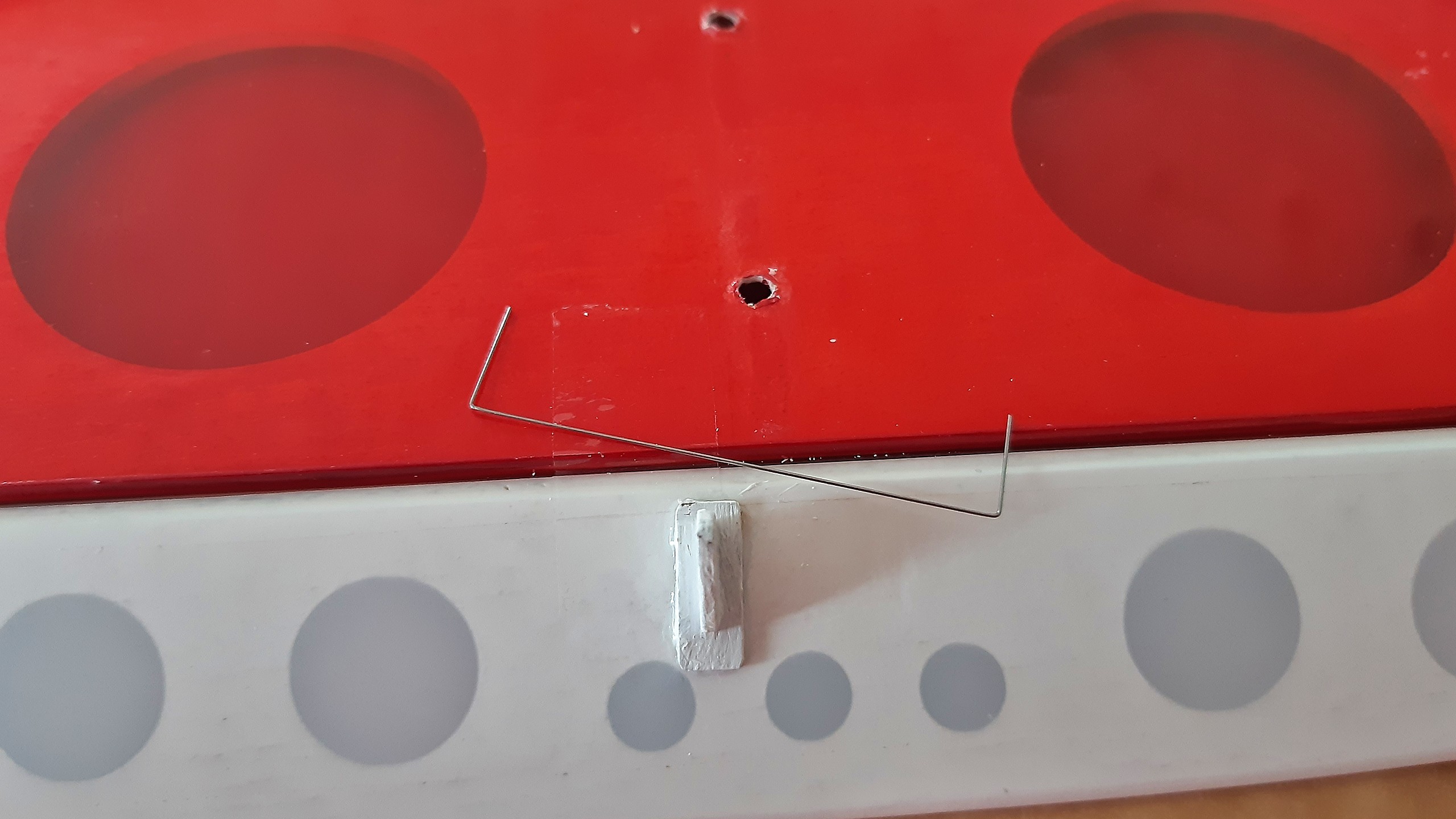
At the tailplane, the control horns need to be glued to the control surfaces, so I first remove the covering around the horn and then roughen up the horn’s base and the surface in order to strengthen the glue joint.

Both control surfaces are linked linked with thin steel wire to work on tension and so they get a torsion spring made from spring steel placed into the hinge. A job quickly done, unless the spring bounces off and one has to find it again…
The centre of gravity was only just reachable without additional trim weights by placing the receiver’s accu in the very front of the nose. There’s only one thing left to do, namely setting up the servos’ deflections and programming the mixers in order to use the ailerons as flaps and spoilers.
Now, the Spin is only waiting for good weather conditions and its maiden flight.