
Now that the tender’s basic construction is finished, I wanted to achieve operational readiness. That required the porter loco to get converted from rail to battery power. The most important thing to keep in mind is to insulate the loco’s circuits from the rails in order to avoid “supplying” the rails with the battery’s current. Only then one is completely independent from other loco’s and can really enjoy the advantages of battery power.
You’ve got a choice, whether you want to do this the quick-and-dirty or slow-and-clean way. The “dirty” solution is to remove the current brushes and shoes from the loco and to use the existing power connectors which provide current for the lighting as an input for the electronic speed controller’s (ESC) current.
The “clean” solution leaves the existing circuit for the most part as it is. You only have to take the motor out of it and insert a switch that determines whether the motor is fed by rail or battery power. That sounds simpler than it actually is because DC-powered LGB locos have quite a minimalistic power circuit: two wires without insulation pick up the rail power, feed it to the motor and also act as connectors for the lighting. So they have to be replaced, or rather complemented in order to allow the input feed switch.
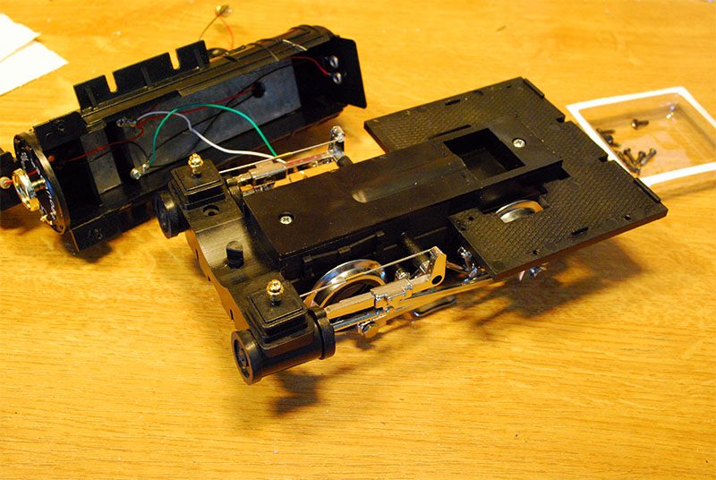
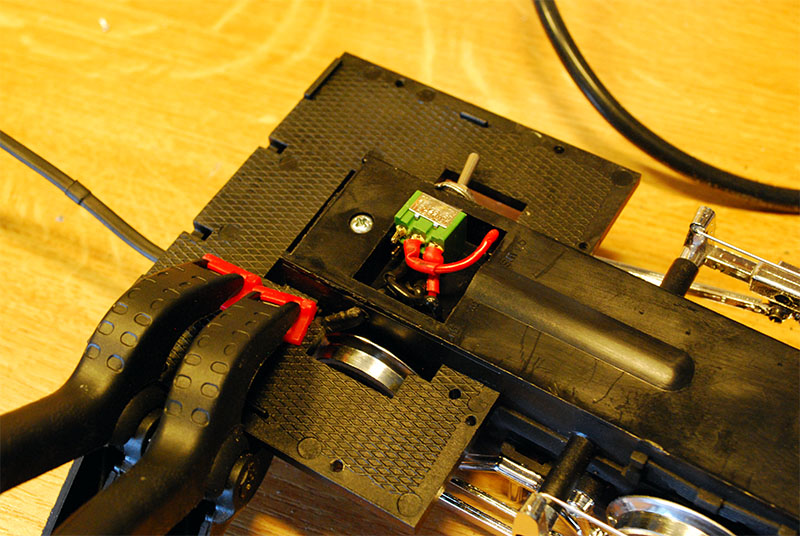
I went for the fast solution, however I did a little groundwork for the input switch, too. At any rate, I removed the shoes between the drivers because they look plain ugly. They were swiftly followed by the current brushes and I borrowed the cable lugs from the lighting curcuit. With their help I connected the input switch that already had been soldered to the battery power cable.
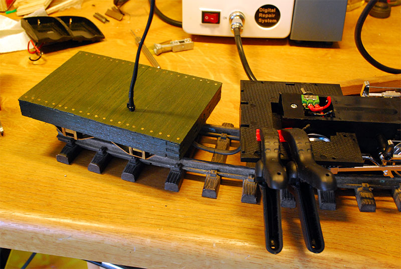
Then I had to pass a test of willpower: the tender’s floor had to be drilled. After I came through with that, the minimum gap had to be determined, so that the tender wouldn’t hit the buffer beam in tight curves. Since I only own the smalles LGB switches (R1) and I won’t be able to change that in the foreseeable future, I couldn’t make the gap as narrow as I’d have liked. However, this can be fixed at a later time quite easily. The power cable was glued to the underside of both loco and tender and secured with metal clamps so it can’t come off.
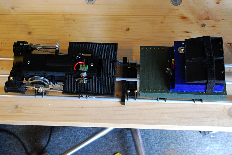
This is what it looks like, after the ESC was connected to the power cable. All that’s missing now is some sort of terminal and plug connection in case one wants to separate loco and tender, although it won’t be needed often. Of course it would have been wiser to make this step at the very end of the process, but I wanted to be able to make some test runs at long last. However, that would require a coupling between loco and tender.