
By assembling the tailplane the construction is finally finished, so now it’s out-fitting the model. As a matter of fact that’s already started since I fitted the aileron servos while building the upper wing.
I’m going to work my way through the fuselage from nose to tail. So today’s topic is set: the engine has to be fitted.
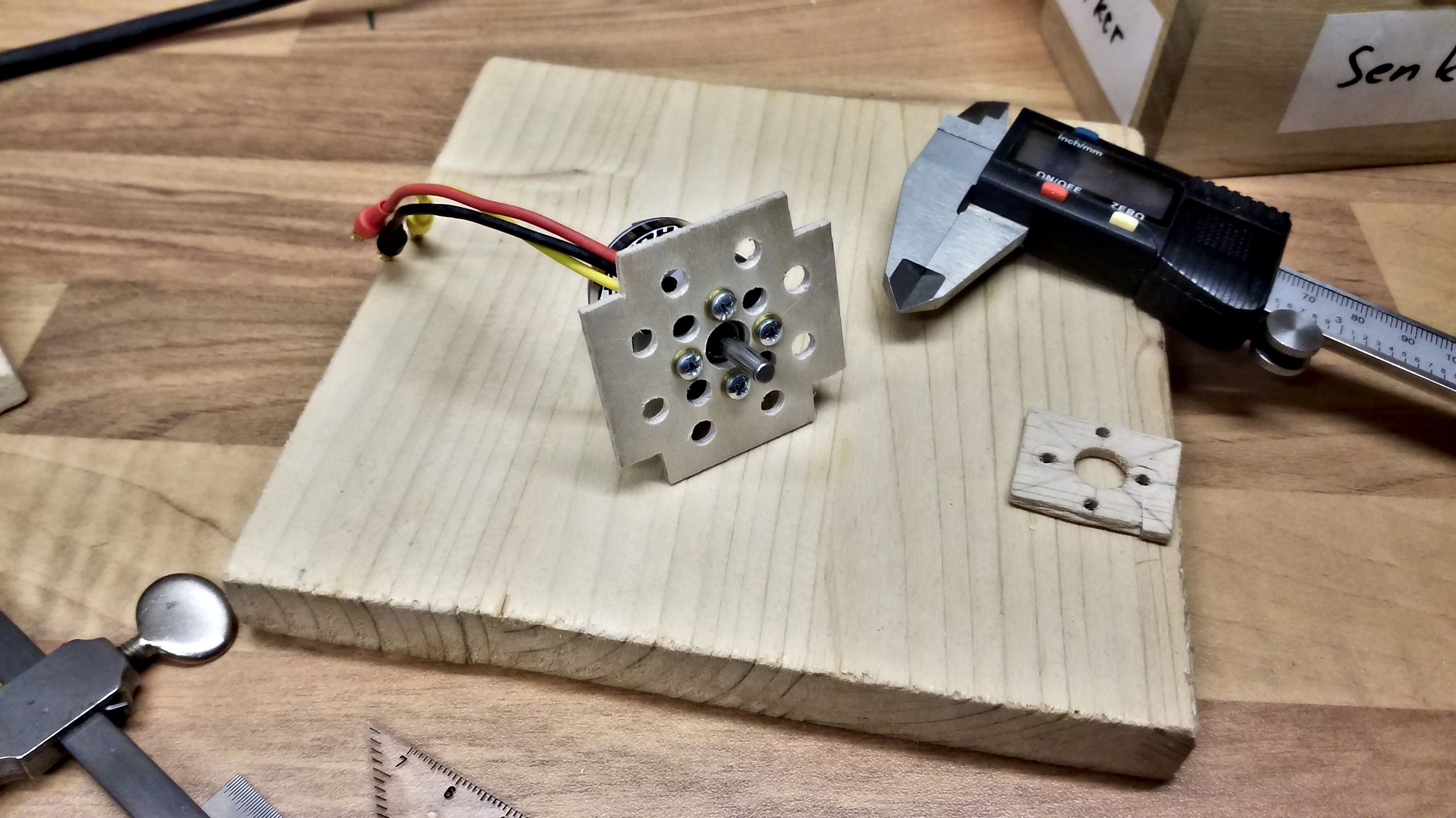
Of course, that will require a frame. I cut it roughly from 2 mm “aeronautical” ply. Next time, I’d use cardboard to make a seamless template and then cut the wood. But this one will do. The frame obviously needs a lot of holes, namely for the motor’s axis and the mounting scews. From a scrap piece of balsa wood I’ve tested the borings’ positions and then transferred those to the frame.
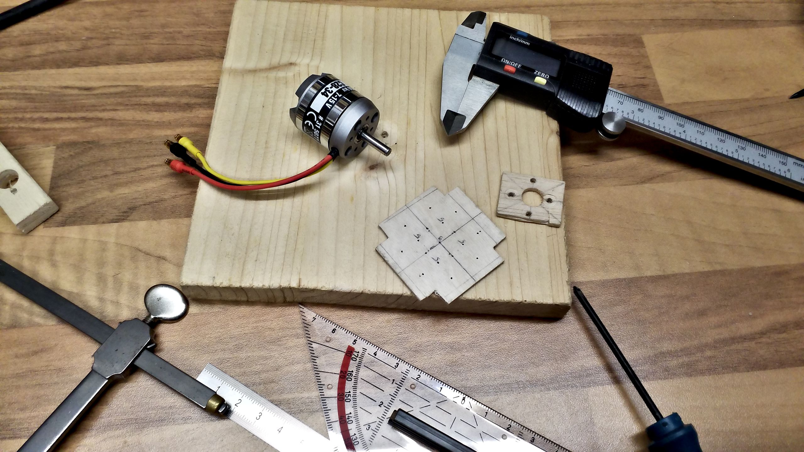
As one can see, I’ve also made a set of holes for cooling purposes. It’s important to leave enough space between the holes so the frame is not weakened too much. To keep things simple, I chose the same diametre as the motor’s air intakes, namely 5 mm, for all cooling holes. The mounting scews have got 2.5 mm and the axis’ outlet needs 9 mm.
As soon as the frame is done, it’s directly glued into the nose. By doing so I’ve omitted the option to tilt the frame to accord for yaw and pitch momentum. (Can anyone help me with the correct terms for “Motorsturz” and “Motorzug”/”Seitenzug”, please?) However, I will knowingly accept this “error”.
First, I haven’t got the foggiest which angles I will actually need. Second, the resulting effects can be trimmed during test flights. And third corrections will be possible by placing washers between the motor and frame. Granted, the prop won’t be perfectly centered then, but I’m not going to be bothered by that. And if it does, I can always rebuild the nose based on my gained experience. (As if I’d really put myself through that…)

It’s time to think about where the remaining propulsion components are to be placed. I’m following two guiding principles: First I want all power cables strictly separated from the R/C’s data bus. And second I’d like to keep the data bus as short as possible.
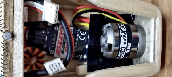
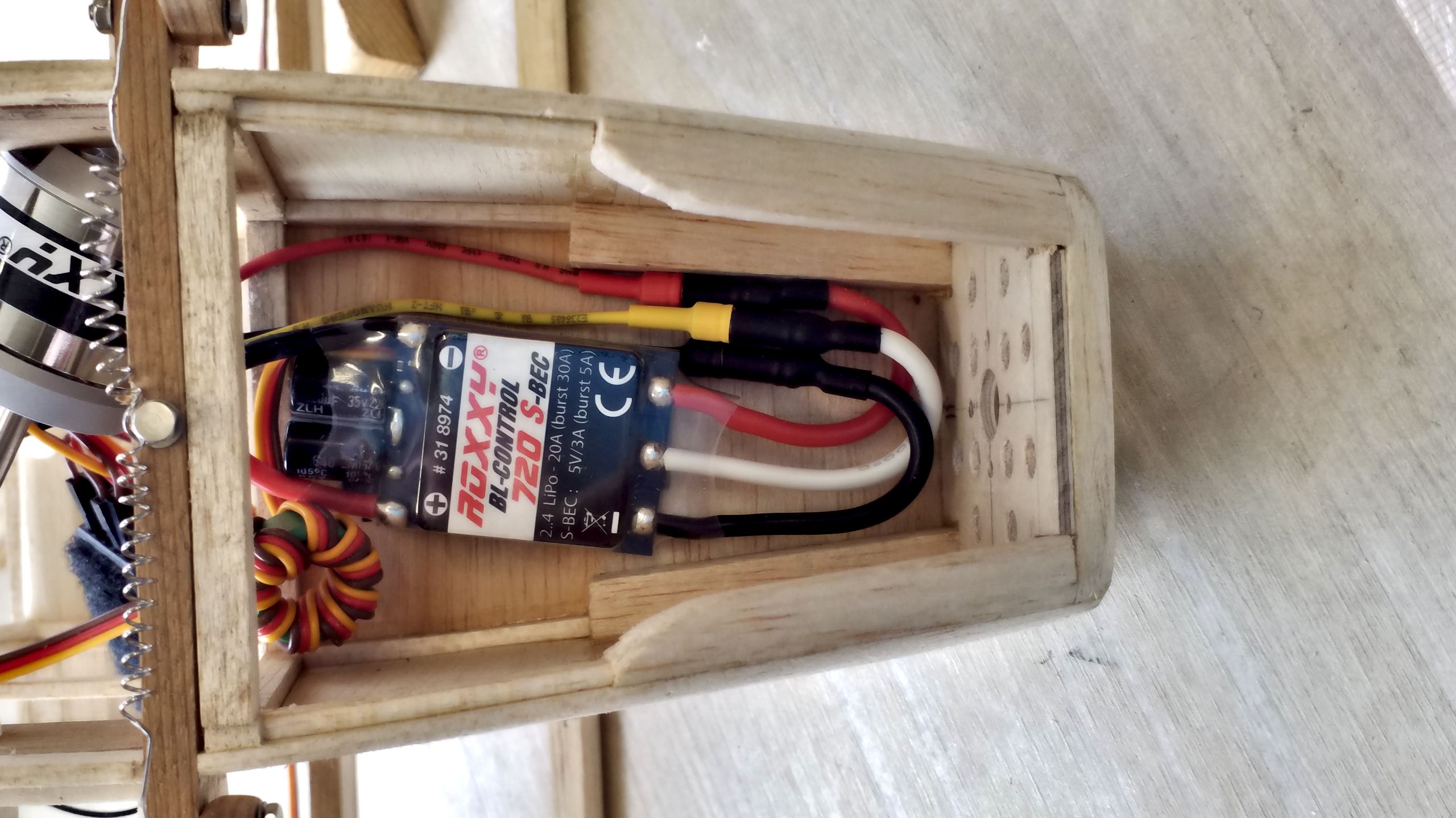
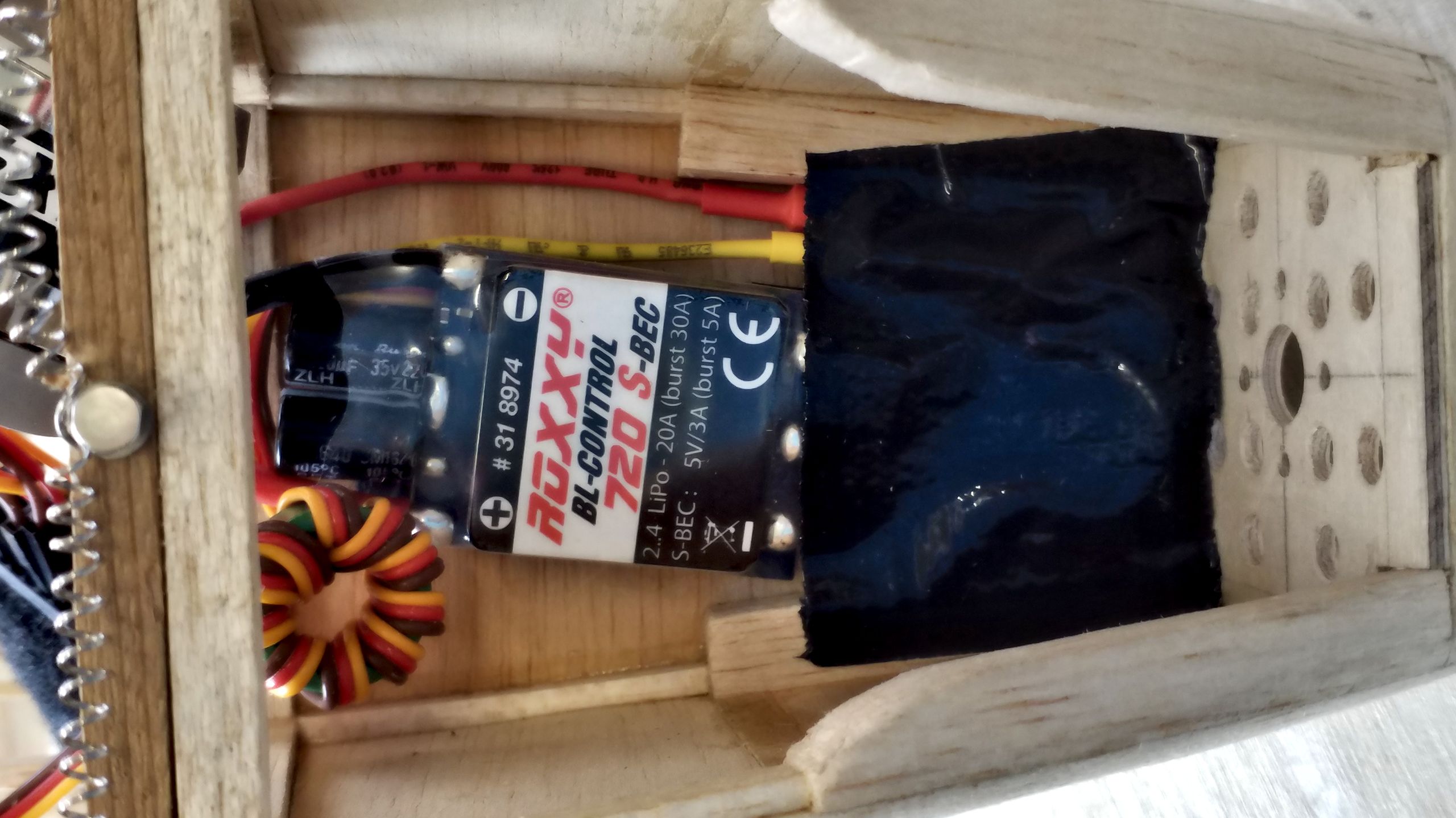
Going through the fuselage from nose to tail, of course the electronic speed control (ESC) has to be placed next. After some to and fro, I’ve put it at the very top of the nose with enough space to spare for the motor’s wiring. For the reader’s guidance: The following pictures show the cowling from “the bottom”.
As one can see, I directly connected the motor and hunted for a good placement of the power cables. As soon as I’m satisfied, the cable is secured with gaffer tape. I’d thought about some pocket made from balsa wood, but it would be too thick. The most important task at hand is to protect the cables from the outrunners’ casing and gaffer tape does the job at any rate.
The process is finished by screwing the motor to the frame.

This leaves the power pack. It is by far the heaviest component because the Joyrider has been given an Easy Glider’s propulsion set. I picked that because on the one hand I’d like to have some thrust reserve for aerobatics and on the other hand I won’t need different spare parts for both models. So the heavy accumulator is going to decisively influence the center of gravity. It’s found its place by the lower wings’ mounting, however the final positioning will be determined at the very end when the fitting-out is finished.
Hence, I’ve constructed an accu box from balsa, which fixates the power pack. I’m not quite sure how to mount the box into the model, yet. Most probably I’m going to clad the fuselage’s belly with balsa and put some velcro on it, so I can easily adjust the center of gravity.
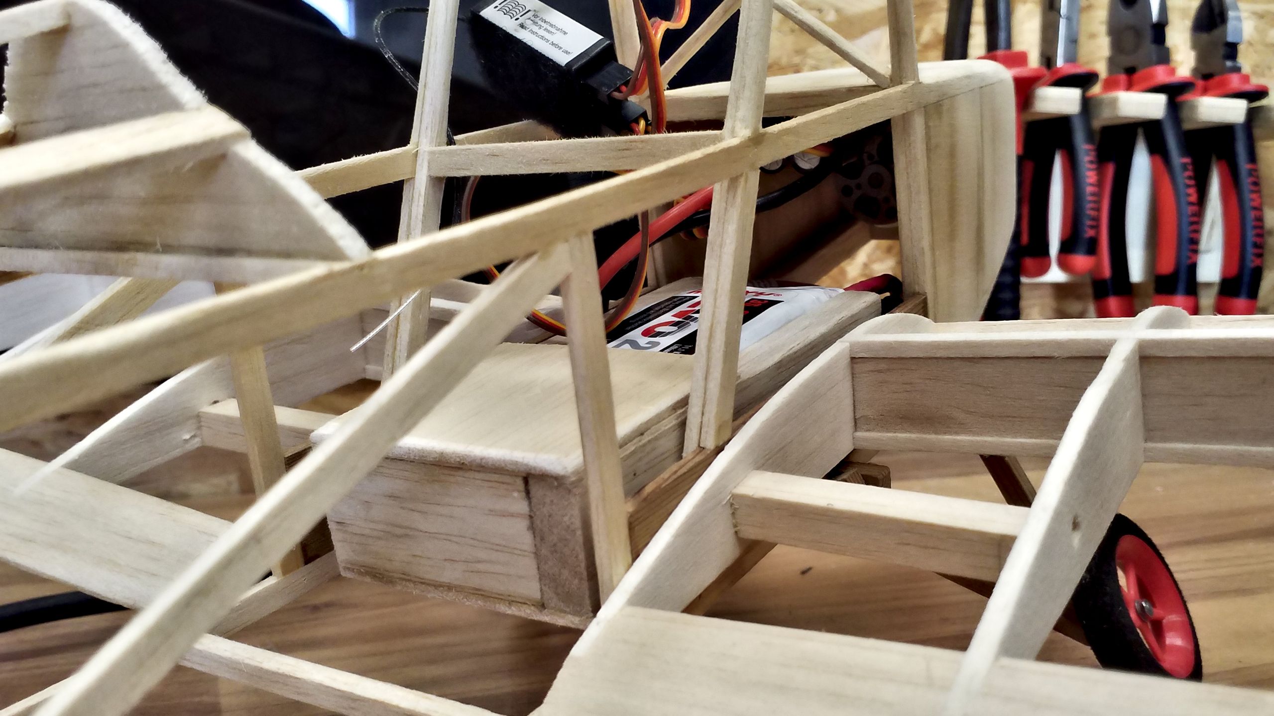
It’s obvious that the undercarriage is brought to its knees by the additional weight. I’d already anticipated the spring to be too weak while constructing the undercarriage – however, one has to start somewhere and this “error” can easily be fixed at the end of the fitting-out.
I simply couldn’t resist. The propulsion had to be tested thoroughly. Many thanks to my wife for operating the camera and to the “jury” for evaluating the test run!
Please accept YouTube cookies to play this video. By accepting you will be accessing content from YouTube, a service provided by an external third party.
If you accept this notice, your choice will be saved and the page will refresh.
So now I’ve got a toy plane that can roll about under its own power. Next up, it has to become steerable, before it’s going to be covered. So next time, I’m going to attack the servos.