
Fitting the engine has sent my motivation soaring, so to speak. So I launched myself at fiting the servos.
Alas, I soon realized that my “planless” construction made my life a tad more difficult. In order to soundly fit the servos, the fuselage has to be reinforced and strutted. I had partially anticipated this and thus constructed the belly with very few slats. Nevertheless I’ve come to realize that one’s way better off if the servo mounting’s fixture is built into the fuselage from the get-go.
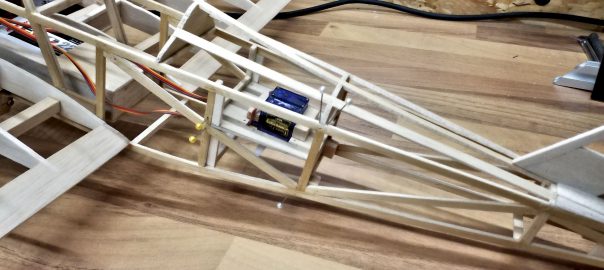
So I started with the aft frame, which I simply reinforced with a small piece of balsa wood, together with two small blocks made from balsa, into which I will glue the bowden cables at a later point.
At the same time I added an auxiliary frame between the existing frames in order to fixate the servo mounting at the front end. On the one hand I wanted to save weight and on the other hand I tried to leave as much open space as possible so I could install the servo cables to the front.
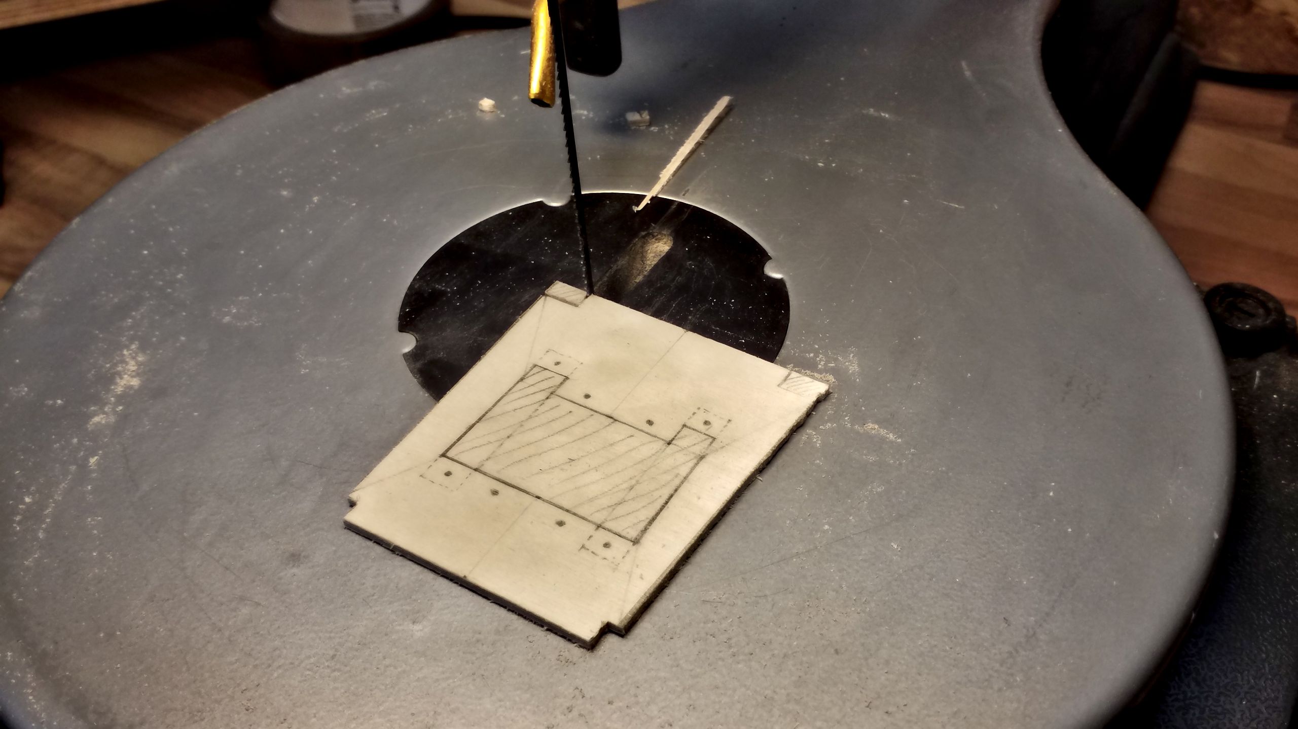
The servo mounting will be fixated between these two frames. It is made from “aeronautical” ply wood, I chose 2 mm thickness. And I managed to complicate my life even more because I wanted to arrange the servos side-by-side in the center. However, my servos happen to have their cable outlet directly beneath one of the mounting brackets. So I’ve planned two slots to the side in order two insert the servos in a tilted fashion and then secure them with screws.
Since I wasn’t too sure anymore whether or not the servos would be securely fastened, I also planned for covering slats which could prevent the servos from twisting free.

As soon as the mounting was marked to the plywood, I cut the form and all necessary slots with my fretsaw.
After that all the holes were bored with 2.5 mm diametre, so the mounting screws would have a tight fit without splitting the wood.

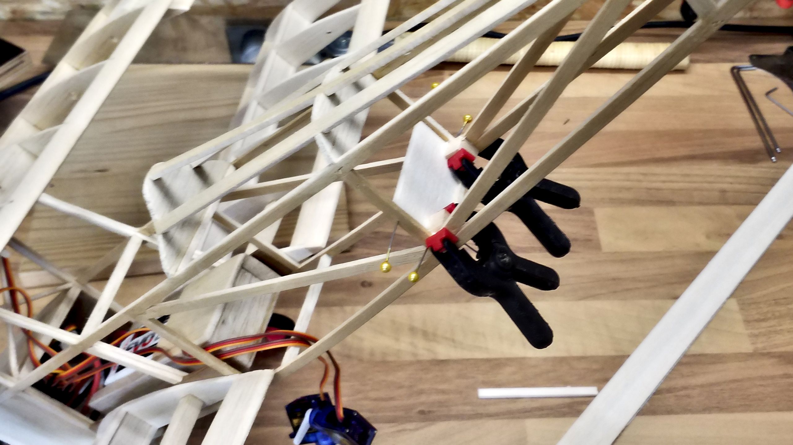
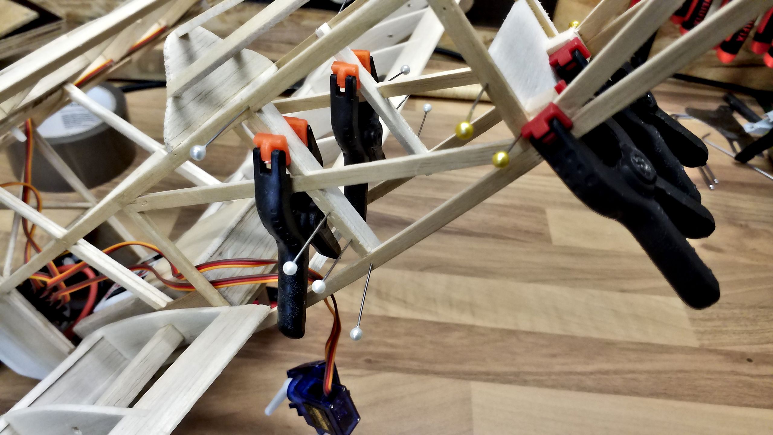
What followed then was quite a fiddly and time-consuming tinkering. The mounting had to be pushed into its position and then glued into place. It seems that I made it too tight a fit, in the end some measure of force was needed and that resulted in some unplanned disassembly. In the picture, you can tell by the pins with white heads where I had to patch up the damage.
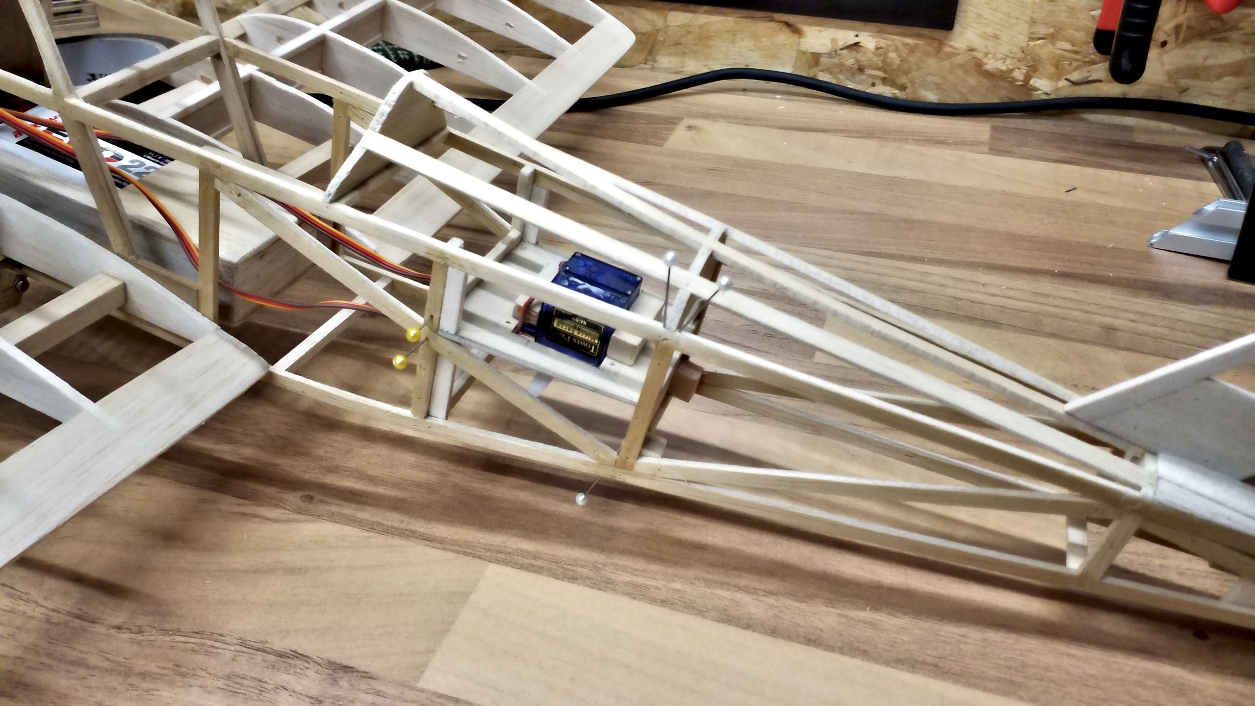
As one can see, the servos are fixated upside down because I didn’t want to cut openings into the fuselage’s ridge. Instead, there will be a maintenance flap in the belly through which I can make fine adjustments to the elevator and rudder.
Finally, the servo cables were laid and connected to the receiver provisionally. A brief function test came up satisfying. So for the next time it’s going to be the linkage to the control surfaces.