
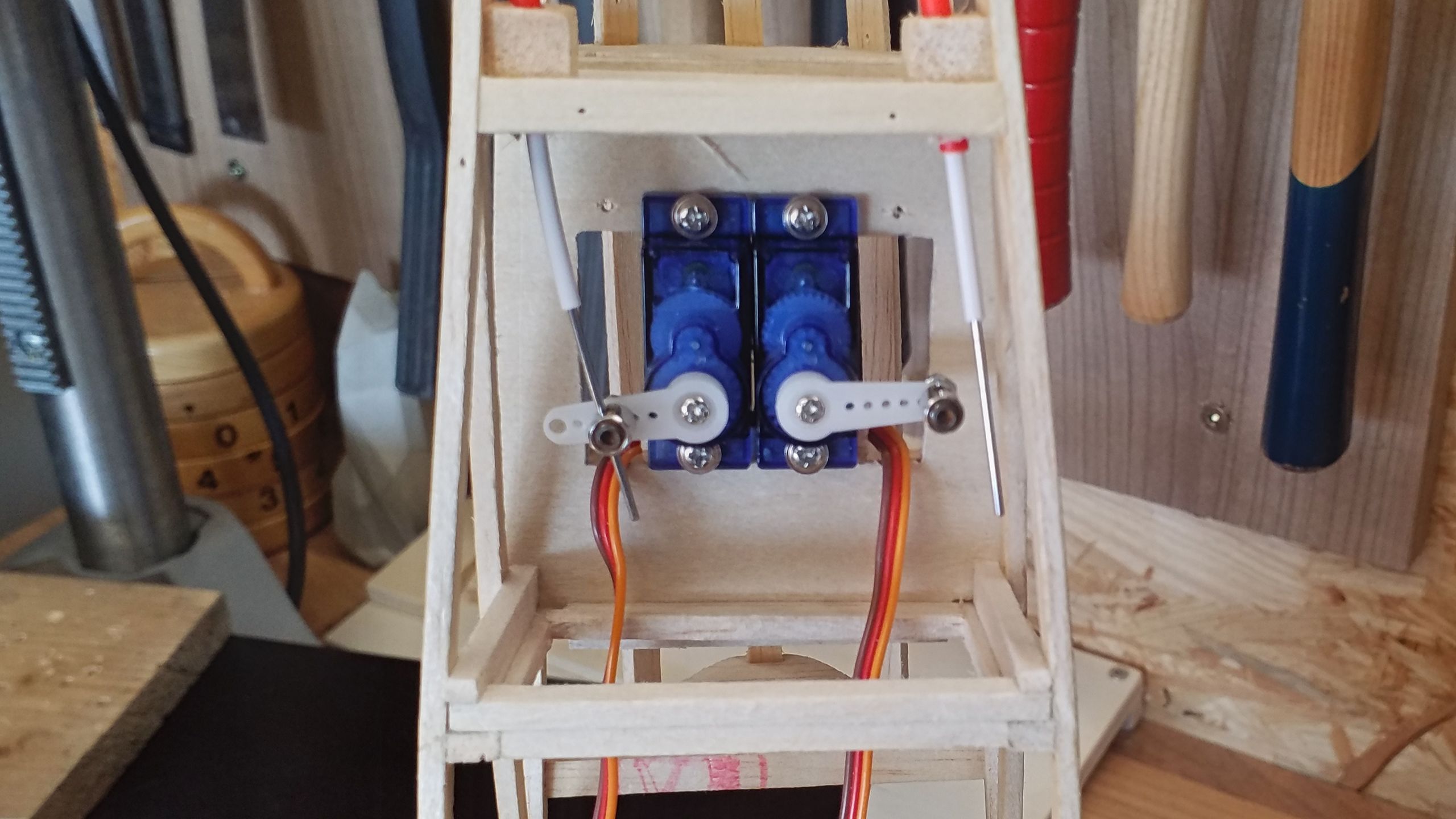
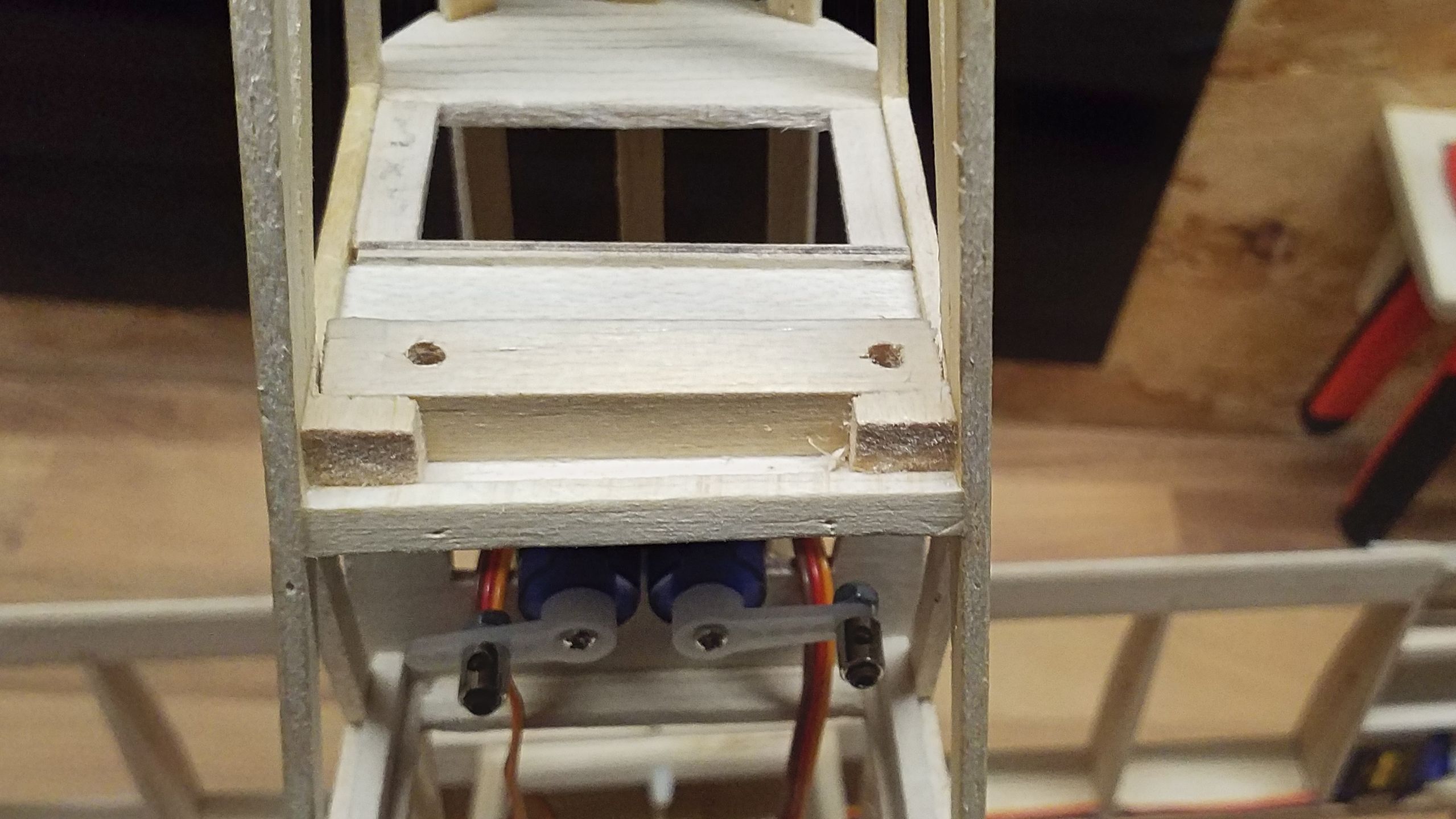
As soon as the tailplane’s servos fitting-out was done I busied myself with the linkage. To start off with, I made a few errors which had to be corrected. I will describe those errors as well as the solutions, so perhaps somebody can learn from my mistakes.
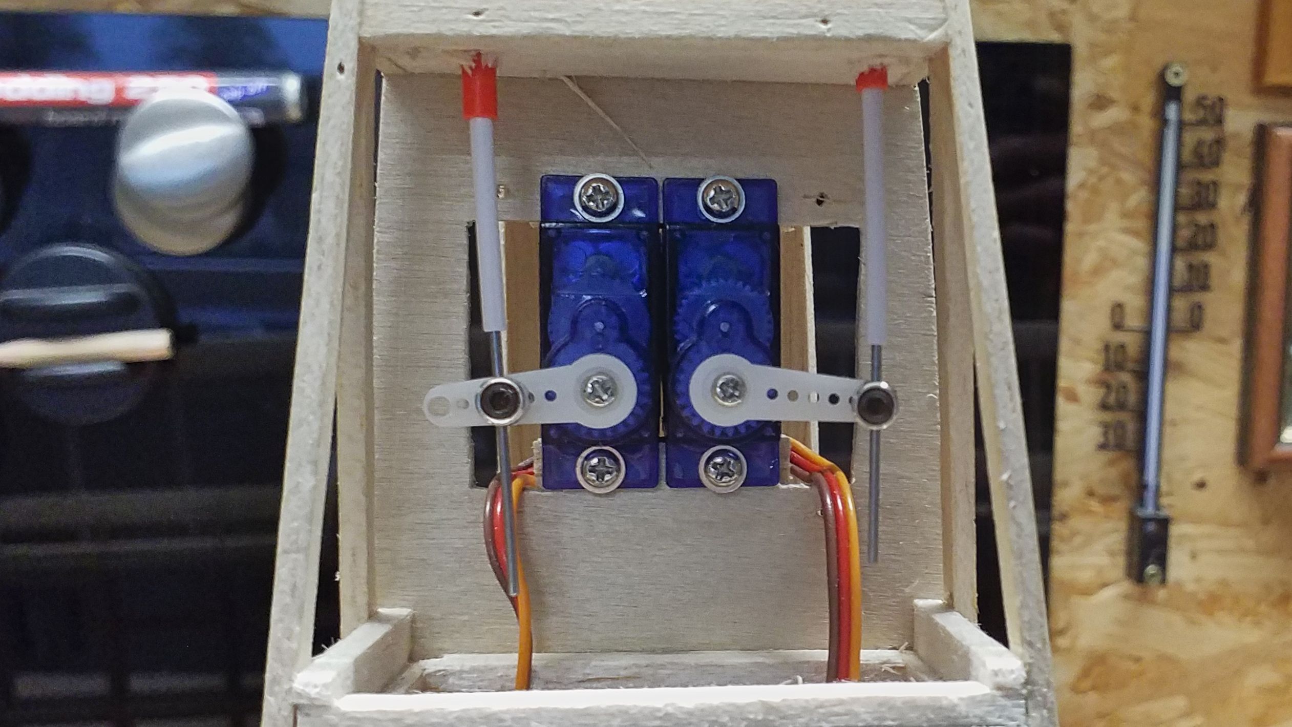
Since I’m not too sure what forces I will have to account for, I’m erring on the safe side. At any rate, I reproduced the linkage used with the Easy Glider and chose a combination of 1 mm steel rod, 2-to-1 mm and 3-to-2 mm bowden tubes.
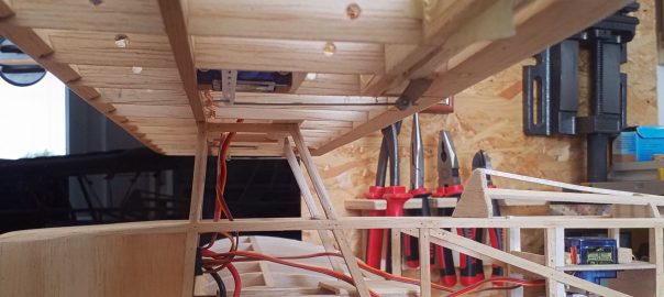
First the positioning and length of the linkage has to be determined. I’d like to finish the tailplane; so I’ve started there and picked the elevator first because it’s the easier one. The bowden cable is supposed to run port (lefthand) along the fuselage and exit at its rear end. Thus an end cap had to be cut to size and bored with a suitable hole.
As soon as I was satisfied with that end I’ve bored another hole into the aft frame at the servos’ mounting and inserted the bowden cable. The end cap is glued into the fuselage. I skipped gluing the bowden cable for the time being – one’s going to see that this will be fortunate, but let’s take one thing at a time.
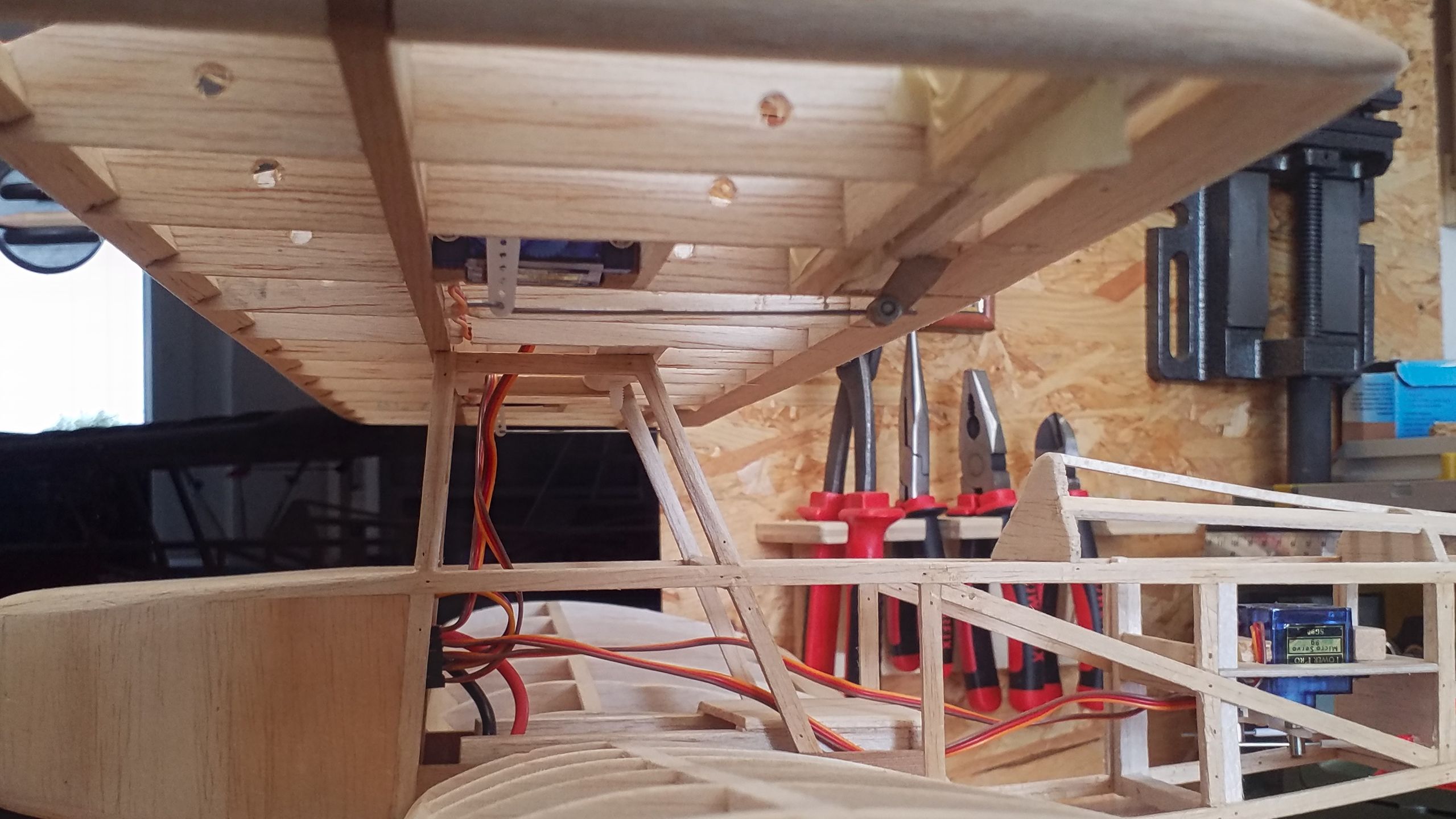
A similar procedure was executed for the rudder’s bowden cable. Here it becomes apparent that the bowden cable has to be lead out of the fuselage in front of the horizontal stabilizer if I want to be keep the option to disassemble the tailplane. OK, this shouldn’t surprise me, but fortunately this can be realized easily. Regrettably the bowden cable has to be bent more than the elevator’s, but the servo should manage.
After the outer bowden tubes were in place, the inner tubes are cut to length, as are the steel wires. I intentionally left some spare length because it’s easy to cut things off – cutting them on isn’t. The linkage connectors allow for easy adjustments through the planned maintenance flap. So far, so good.
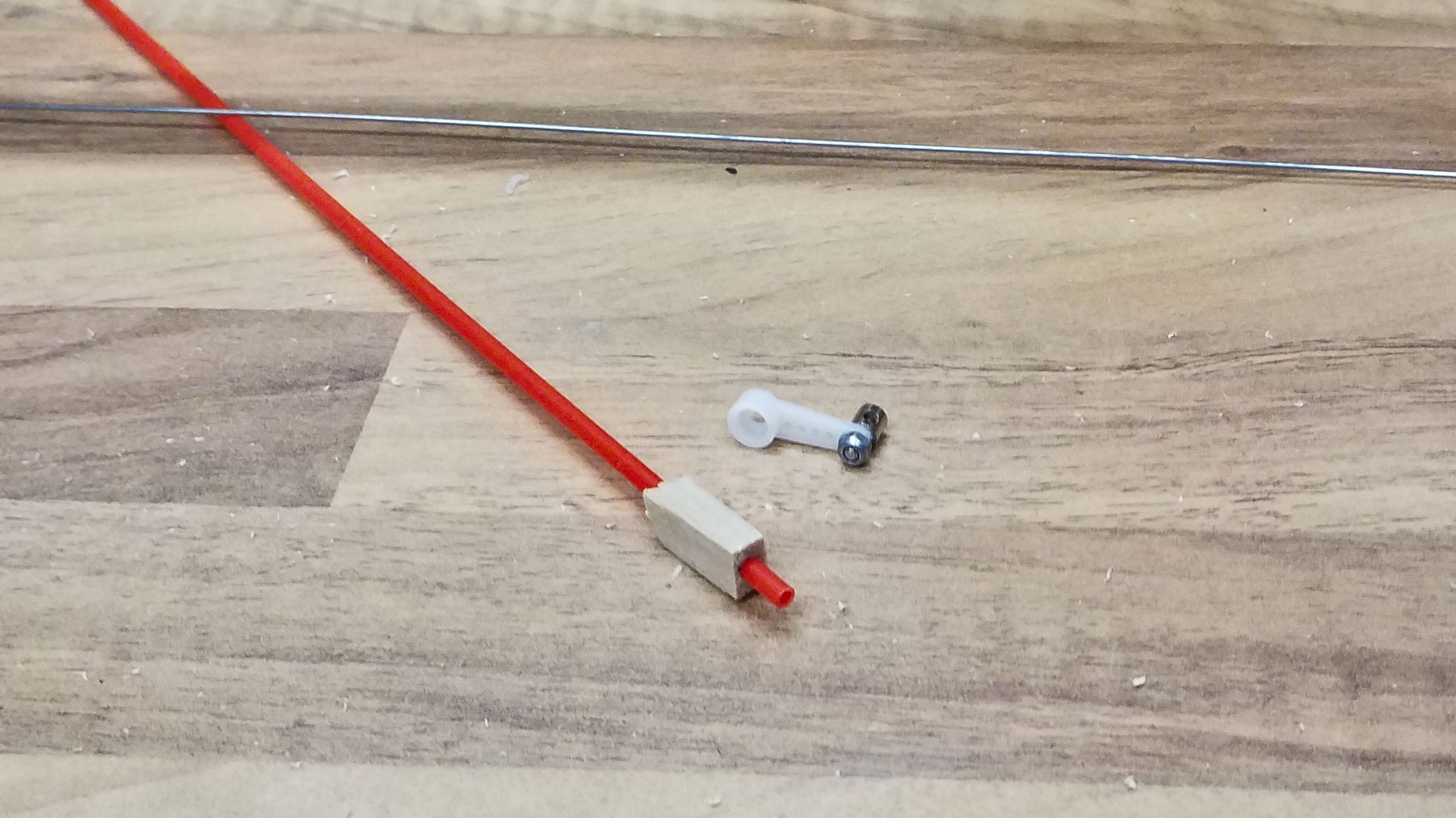
It wasn’t until a few minutes afterward that I realized just how much the bowden cables were bent. The reason is simpel: I had them passed through the frame at a roughly planned spot and not in their optimal position. And now it dawns to me: the servos have to cope with these forces. That’s not good! Even if they prevail for the moment, it will cost lifetime for the gears, axes and bearings. Und I’ve already had an aileron malfunction due to a faulty servo. I don’t want to experience that with the rudder or elevator! So, subsequent work was in order.
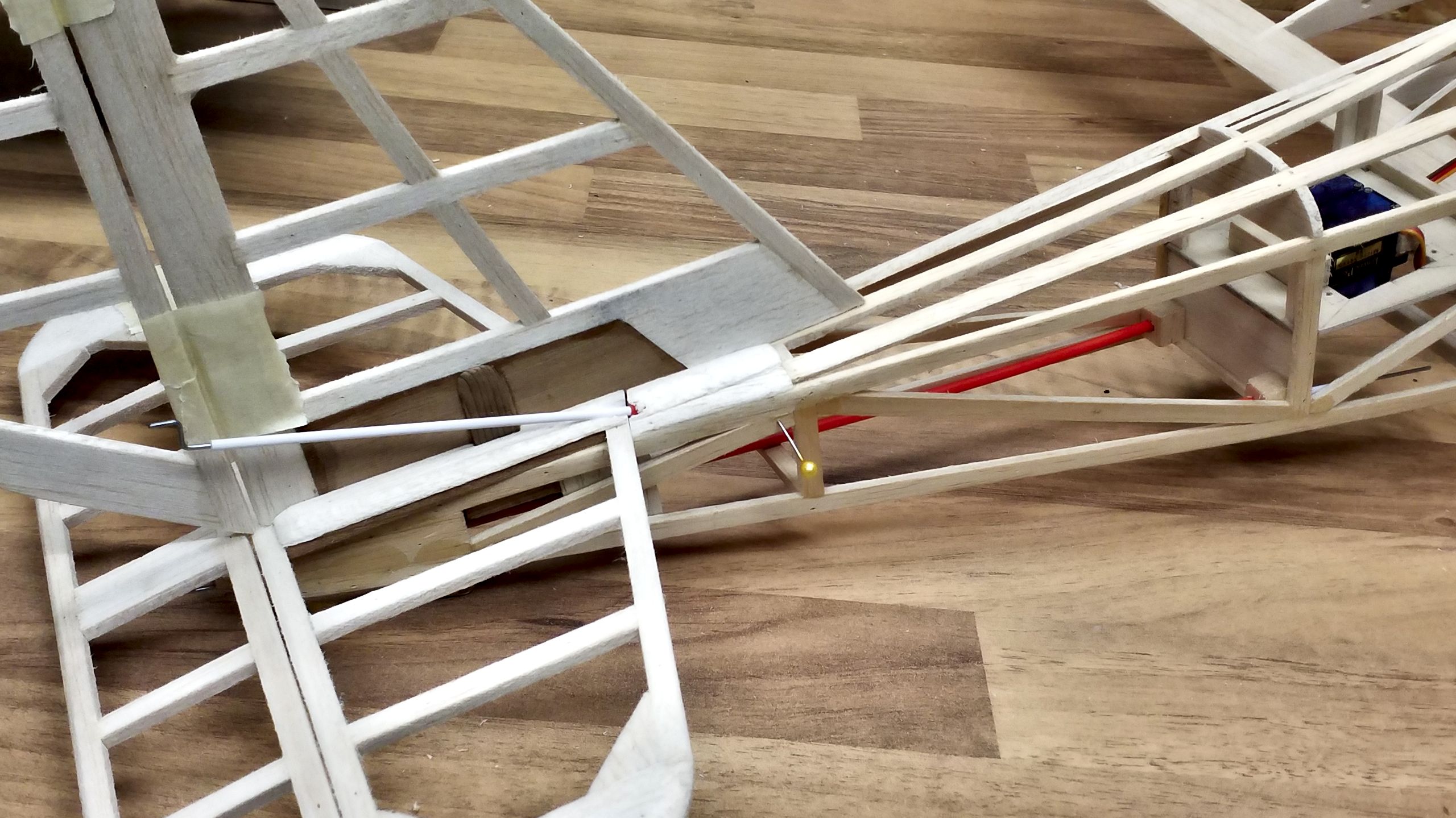
In order to get some effective results the bowden cables should be positioned laterally as well as vertically to the servos. The lateral distance needs to account for the actual lever way, so I need to find out that one first. Hence, a lever horn was cut and fitted to the elevator.
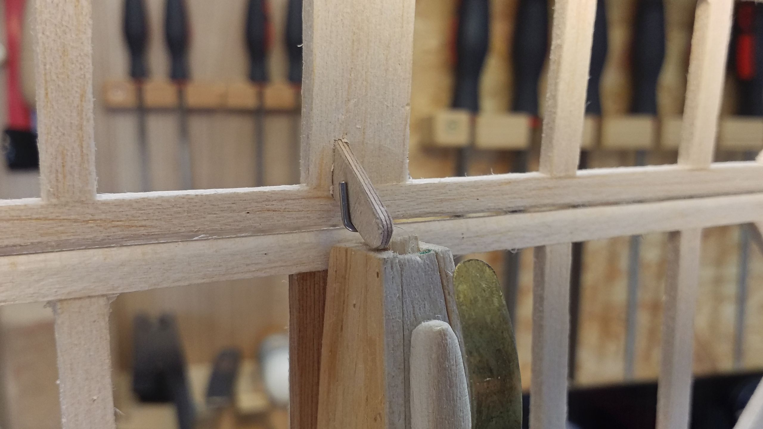
The horn is angled in such a way that the linkage hole is preferrably placed directly above the hinge-line. Thus it allows linear deflections. I will limit the servo’s deflection via the transmitter’s digital mixer. That will cost me a bit of fine control on the elevator’s joystick, but to me that’s an optional objective for a later time.
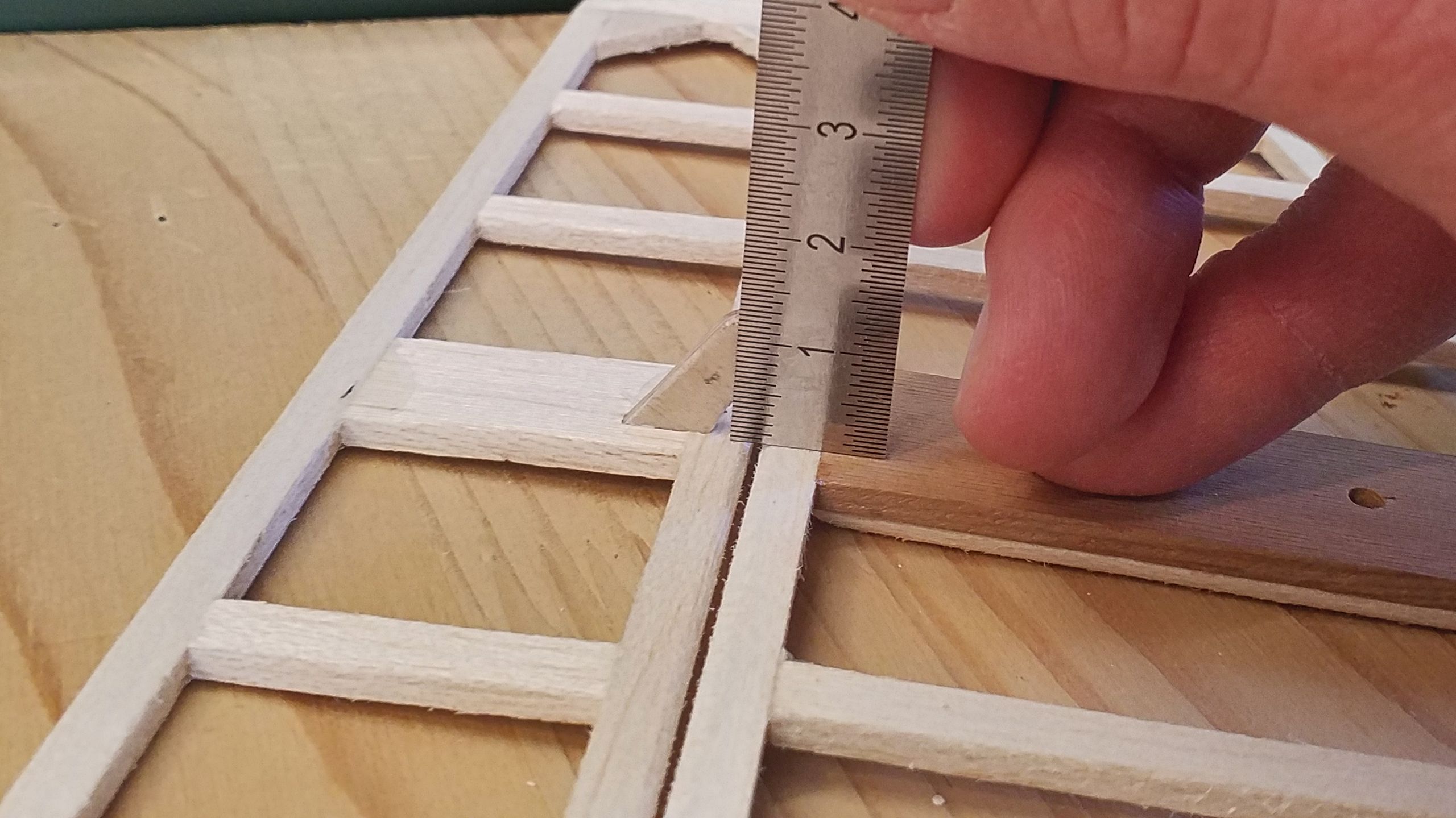
As soon as the horn is in place, the assumed boring position is marked and then the lever way’s length can be measured.
At the tailplane’s end of affairs, the fuselage has to be adjusted to the new reality. In order to allow for the elevator’s downwards deflection, the fuselage has to be trimmed at an angle. Well, cutting off is easy…
The rudder is treated the same way, a horn is cut and fitted out, then the distance is measured.
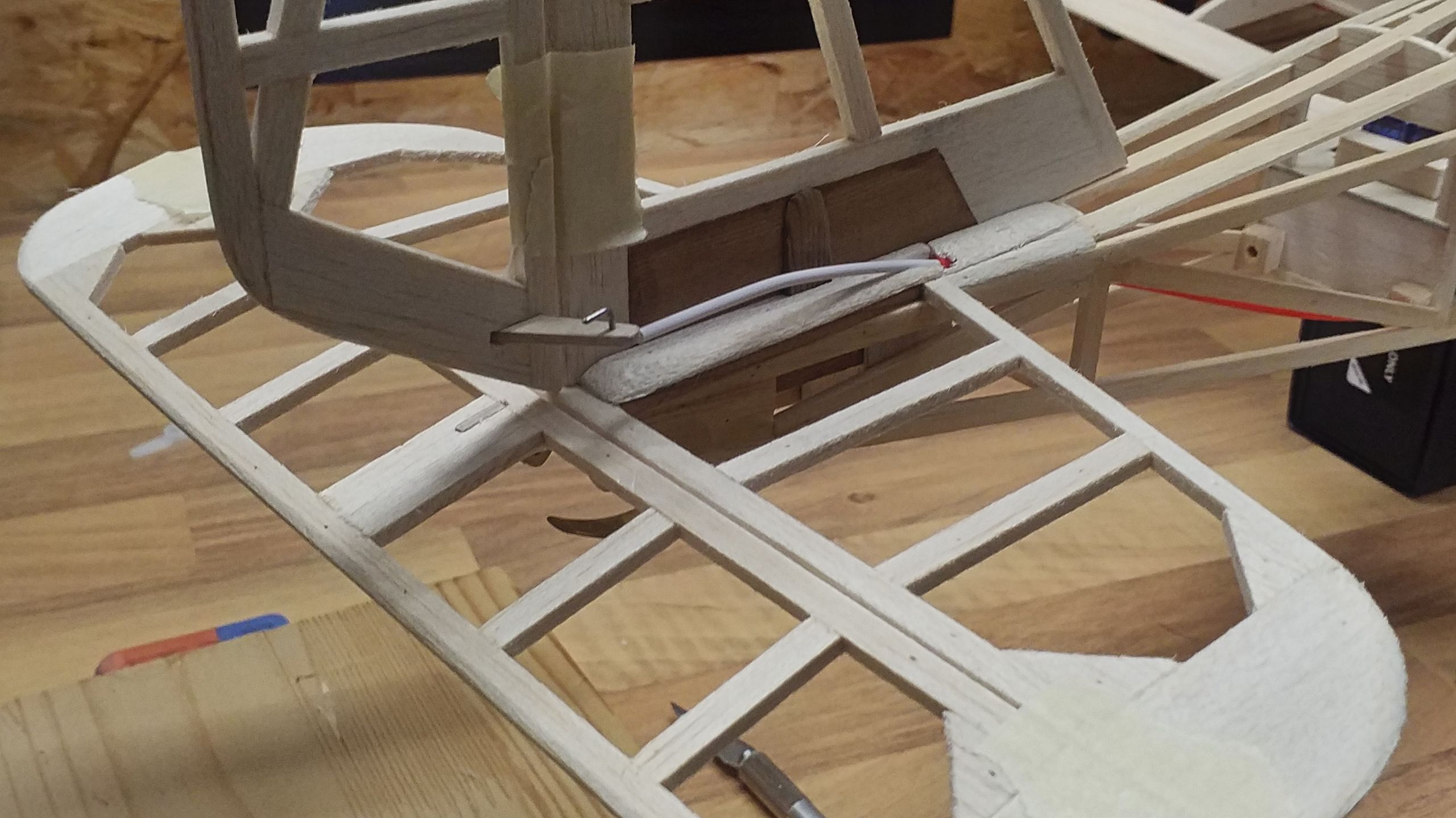
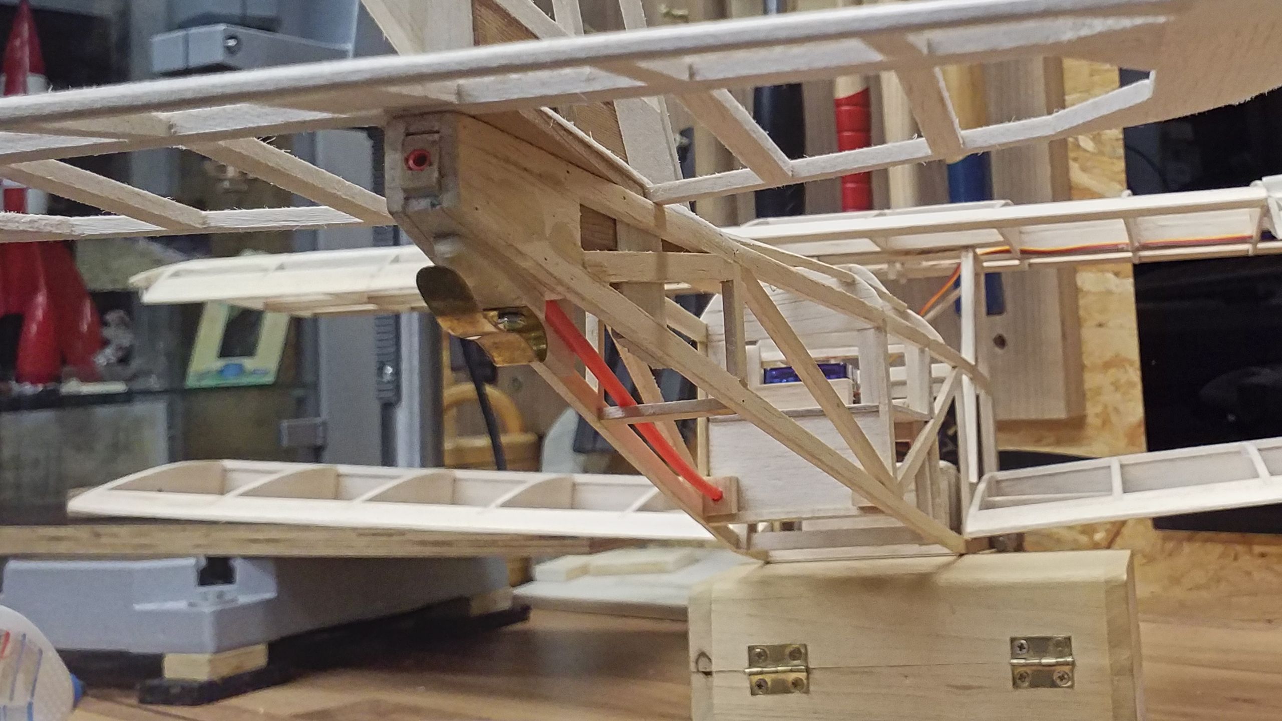
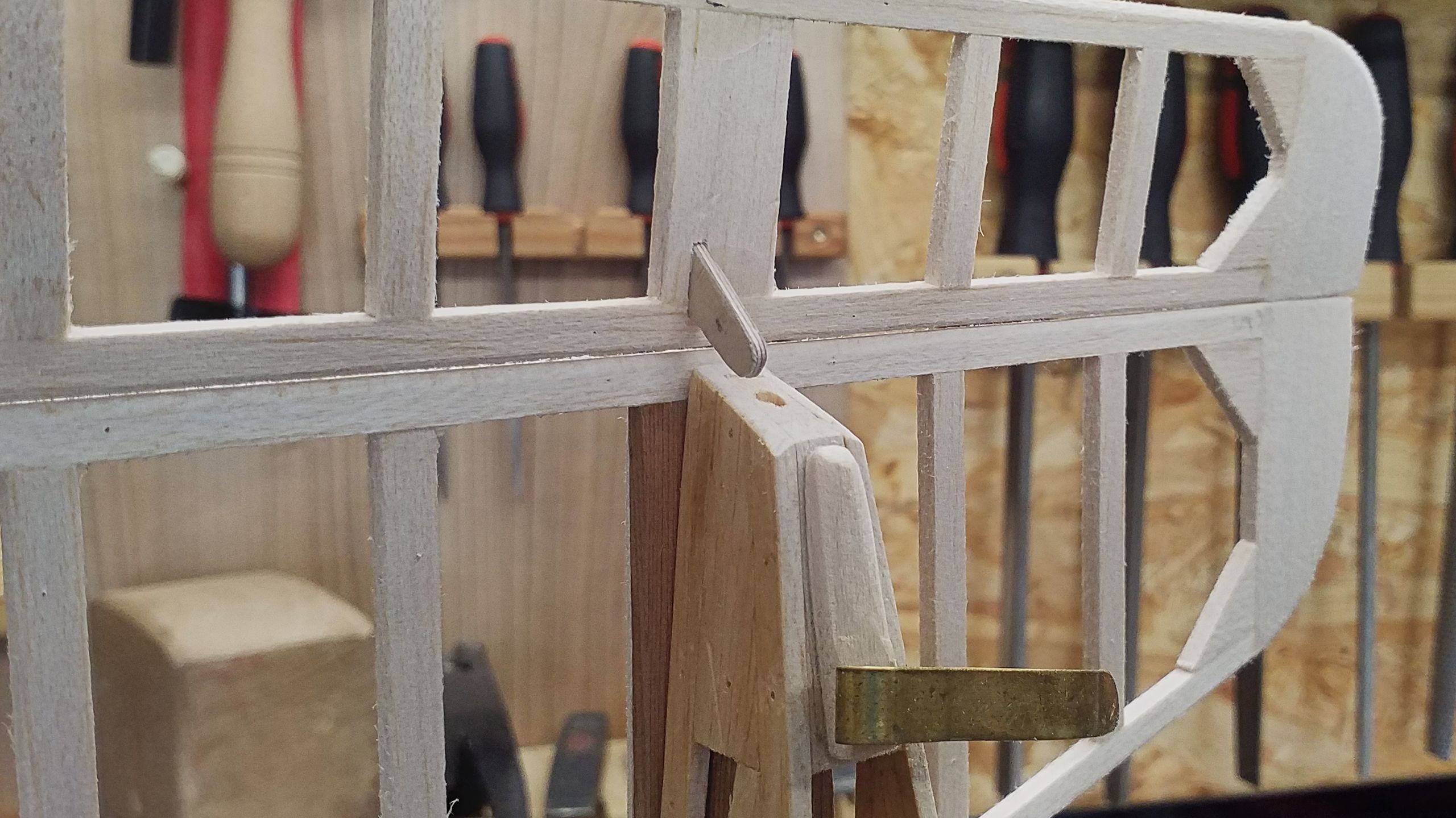
With these preparations done, the tail plane’s fitting-out is completed and all there’s left to do is correcting the borings for the bowden cables at the servos’ frame. Thanks to the measured distances a supporting slat is bored. Then it’s placed at the front side of the frame at the correct height to mark and bore the holes.
Thus the positioning of the slat is easy and at long last it’s glued to the frame’s backside.
As one can see, the bowden cables are only slightly bent now and the servos have much less to endure.
Compared to the tailplane, the ailerons are a walk in the park. Some horns are cut and glued into place, the linkage is done with some short pieces of steel rod.
All in all, this step was a lot more time-consuming and nerve-wracking than I had anticipated. On the other hand, that’s one of the fascinating aspects of scratch-building, you learn a lot of new things and meet new challenges.
The fitting-out is coming to its end. Next time, I’m going to strut the wings and add some planking to the fuselage.