
Our Summer Operation Session was a lot of fun, but most of all it was informative. I learned three very important lessons concerning my flatcar prototype:
- Frame-mounted couplers need large radii
- Bogies need clearance for operational reliability
- Bogie-mounted couplers increase reliabilty
Alas it came to light, my test waggons are way more forgiving than the rigid frame of an actual flatcar: even with R3-radius curves (2,390 mm of diameter, no less!) I struggled to move the waggon without any derailments. There are three reasons to it:
The obvious one is that frame-mounted couplers can only marginally swivel. So one needs large radii. Since I’m going to operate my trains on other people’s layouts most of the time, I can’t just expect the tracks to accomodate my waggons. So the waggons will have to adjust to the layouts.
Not quite as obvious is the fact that the bogies mustn’t be fastened too tight. One has to allow for some play to compensate for the tracks’ imperfections. That adds up to a three point support. If one ignores this requirement, the wheelsets are lifted off the track and due to the low flanges derailments follow quickly.
Lastly, there’s one thing that I hadn’t figured out before: Mounting the couplers to the frame means that the bogies have to find their own way. When entering a curve, the first wheelset is displaced laterally, the resulting torque turns the bogie into the curve. Just another challenge for the low flanges. Mounting the couplers to the bogies ensures that the leading waggon guides the bogie, which is literally pulled into the curve. Thus derailments happen far less often. That’s a new one to me!
It can’t be helped, as long as I don’t build my own, perfectly constrcuted layout, the couplers have to be mounted to the bogies. But what about the height of the couplers? Fortunately it turns out that I can simply flip the mounting boxes. The couplers lose only a few millimeters in height compared to the frame-mounted option and I can live with that!
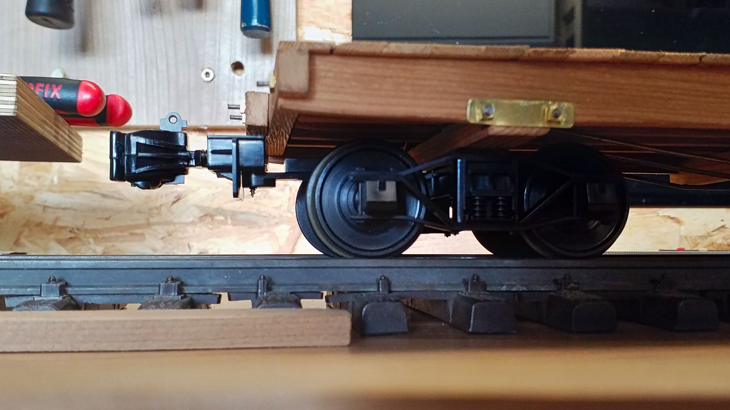
Of course the couplers can’t just be fastened with one flimsy screw. So a reinforcement is in order, made from small blocks of red cedar. The prototype would sport the draw timbers at this place, so I don’t have to overstrain the modeler’s license.

The first static test finds the construction to be somewhat plausible and the mounting boxes can now be fastened to the draw timbers. That will make sure that tension and thrust are passed on without building shearing forces on the mounting boxes.
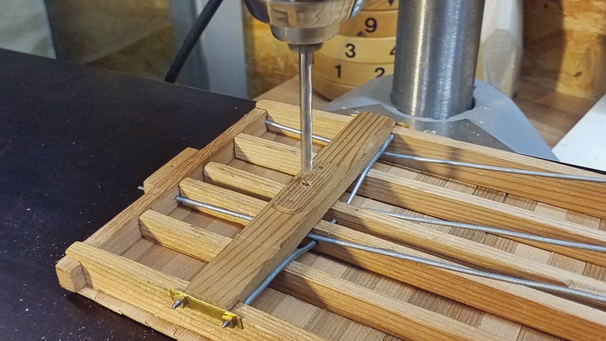
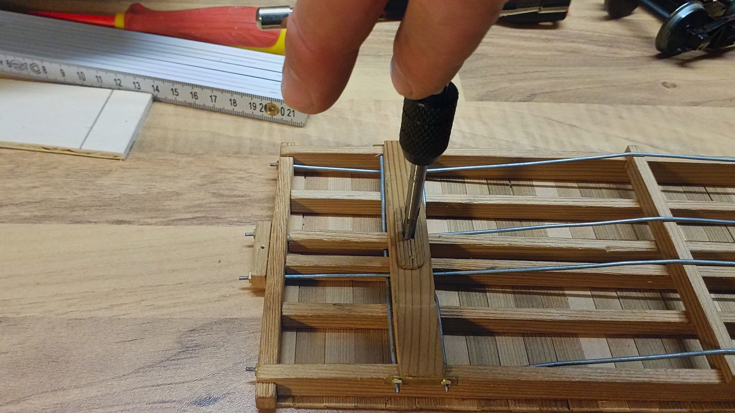
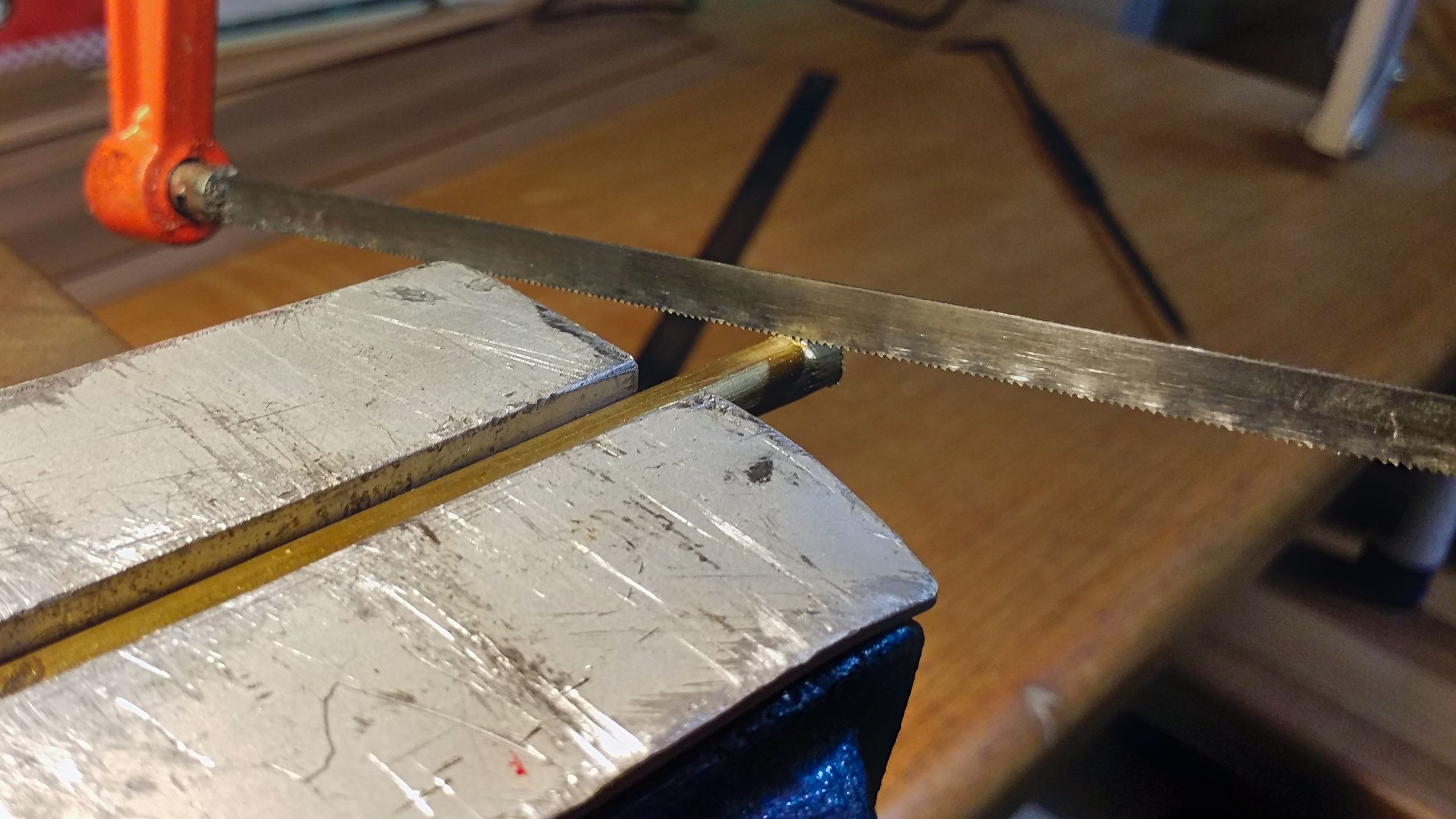
As a consequence the bogie mountings are suddenly becoming very important, in case of doubt the whole consist will tug at those. Until now, I’ve used simple woodscrew of 3 mm diameter, that won’t do no more. First off, the body bolster’s boring is enlarged.

This boring receives an M5 thread. This thread is then hardened using superglue, quite a neat trick I’ve learned from constructing model aircrafts. Why M5, you ask? We’ll come to that.
Since Piko’s bogies are cast from plastic, they won’t withstand the sharp edges of a threaded screw. These bogies have a boring with a diameter of 6 mm; they are supposed to receive a 6 mm king pin, which is secured with a washer and plasticscrew. I’m flipping the concept: The boring will receive a brass bearing bushing with a wall thickness of 0.5 mm.
This bearing bushing is pressed into the bogie. Of course, now there’s only room for a M5 threaded screw which can’t damage the plastic bogie any more.
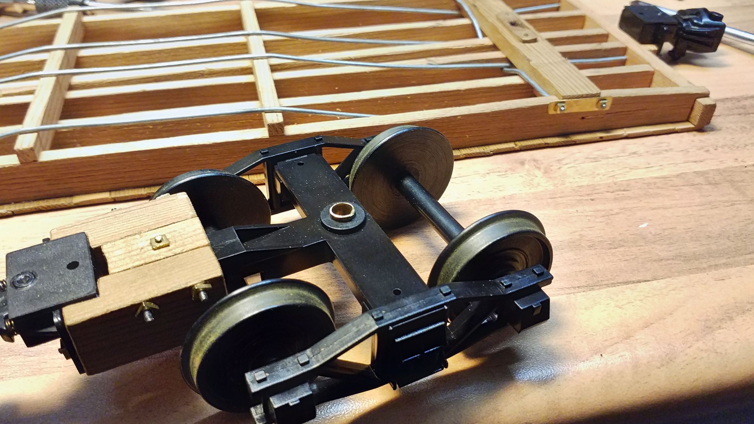
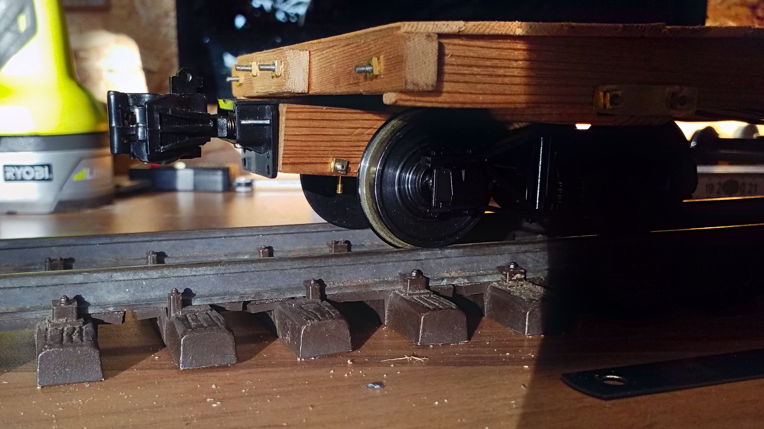
The bogie is being mounted with a stainless steel M5 Allen screw. The lesson learned during the operation session is applied and some play is allowed so that the flatcar keeps contact to track on less-than-perfect layout sections.
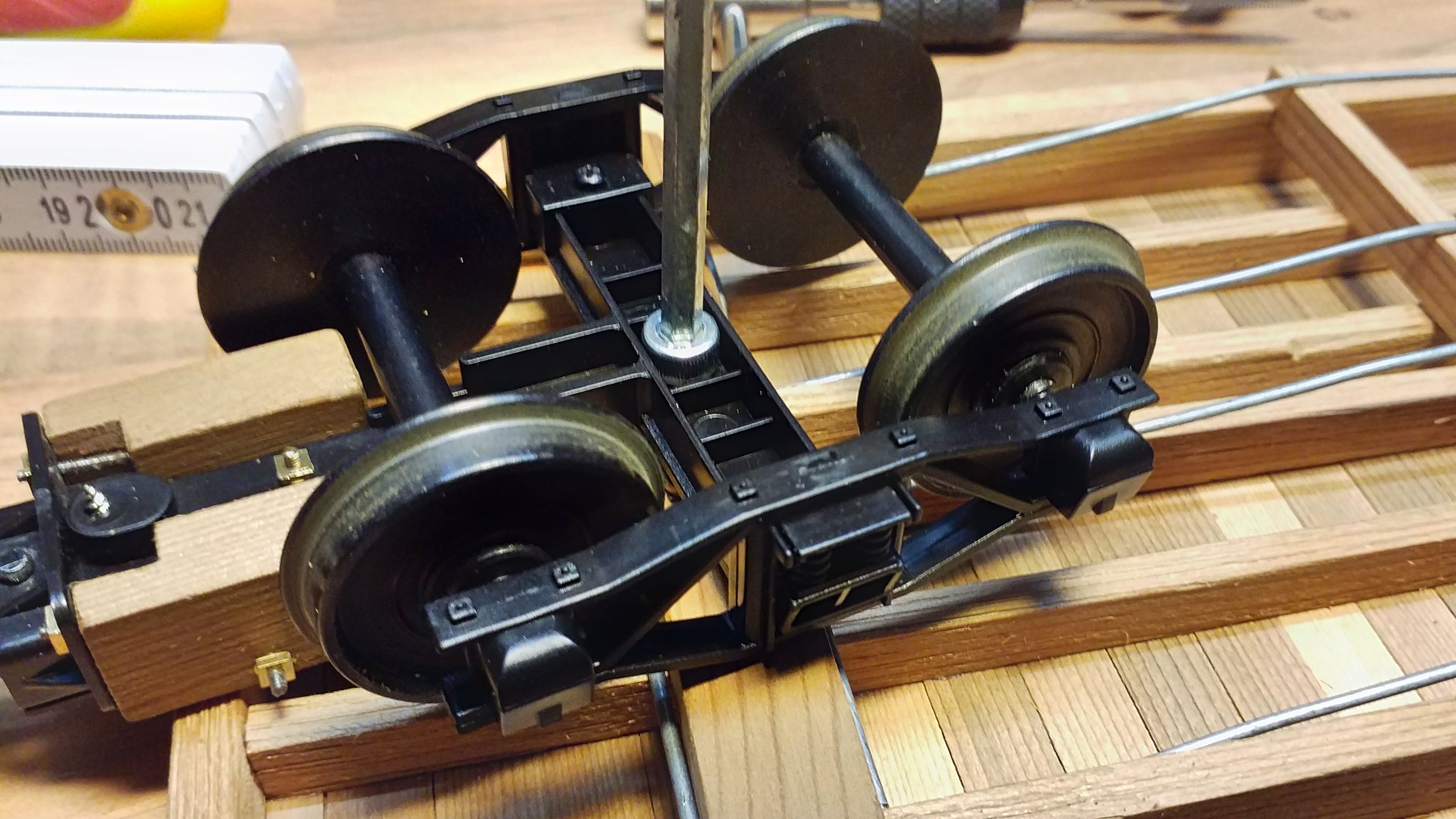
A short test run on some snap track shows that these adjustments bring good results. So it’s definite that all my waggons will be constructed with bogie-mounted couplers. And I can later convert them to frame mountings, if I ever get to build my own layout.
And once more it just shows that one has to make compromises. However, I can happily live with this one.
Update: Meanwhile the second coupler has been mounted to the bogie.