
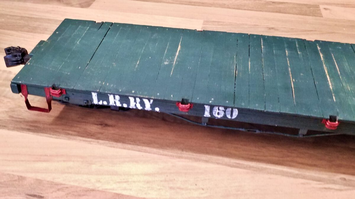
After finishing the stake pockets, I’d like to address the lettering. Encouraged by the good results of lettering the freight crates, I’ve created stamps for the railroad company, waggon number and some technical numbers. And I managed to find flexible 3D printing filament, namely TPU.
Category: Rolling Stock
Flatcar Prototype: Stake Pockets
By constructing the steps the flatcar has gained some character, but of course this can only be the beginning. The next topic is to build the stake pockets. I’ve already constructed stake pockets for my porter’s tender and gained some valueable experience. I’ll profit from it while moving on.
Flatcar Prototype: Steps
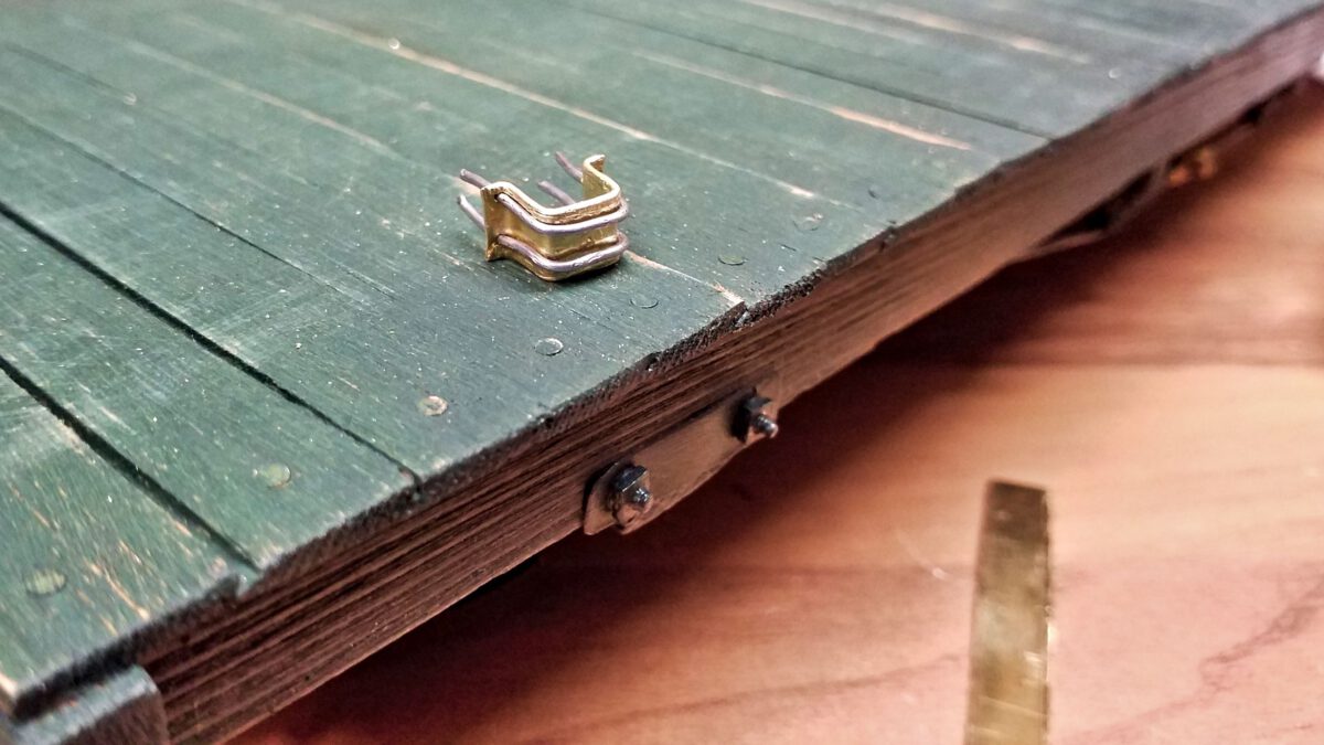
After the flatcar has got its turnbuckles, the next step will be… well, steps so the Lead Road Railways’ conductors don’t have to do so many pullups any more.
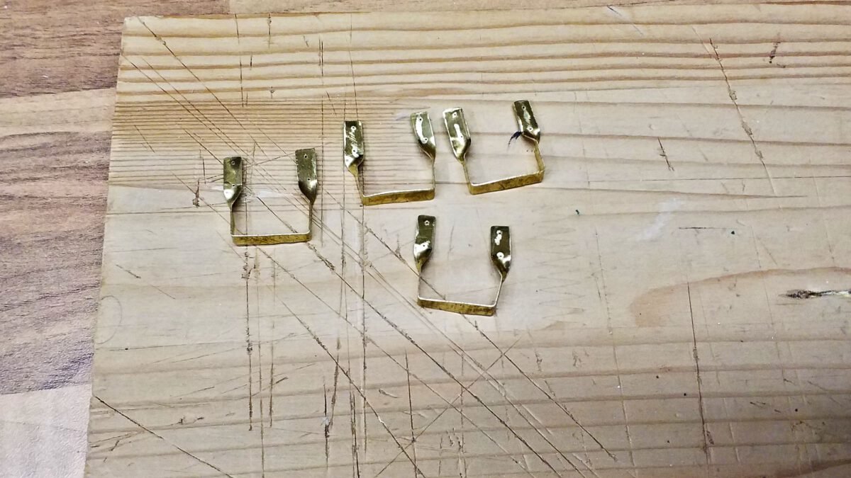
I’ve already built steps for my porter’s tender, so these are charted territories for a change. In fact I took the tender’s steps’ measurements and copied them as a small batch.
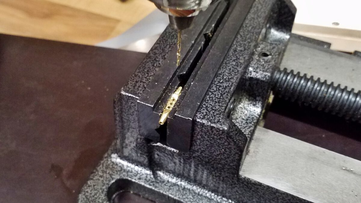
And since I didn’t show much about how I made those steps, this time I’d like to give a detailed report.
Flatcar Prototype: Turnbuckles
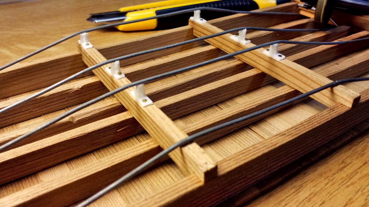
By mounting the queenposts the waggon’s substructre is now ready for the turnbuckles. The prototype is used to adjust the trusses’ tension in order to avoid the waggon’s floor to sag. I decided to go for a scratch-build again, since the cast pieces are currently very hard to come by and on top of that they would have been the weakest link in my current construction. However, as a matter of fact it’s very time-consuming to build them manually.
Flatcars Prototype: Detailing the Underside
After busying myself for a while with the bogies and couplers, it’s time to start detailing the flatcar. Though they are not that striking at first glance, the details will significantly add up to the overall picture. And since they are the most visible parts, I’m starting with the trusses or more specifically the queenposts.
Flatcar Prototype: Bogie-Mounted Couplers
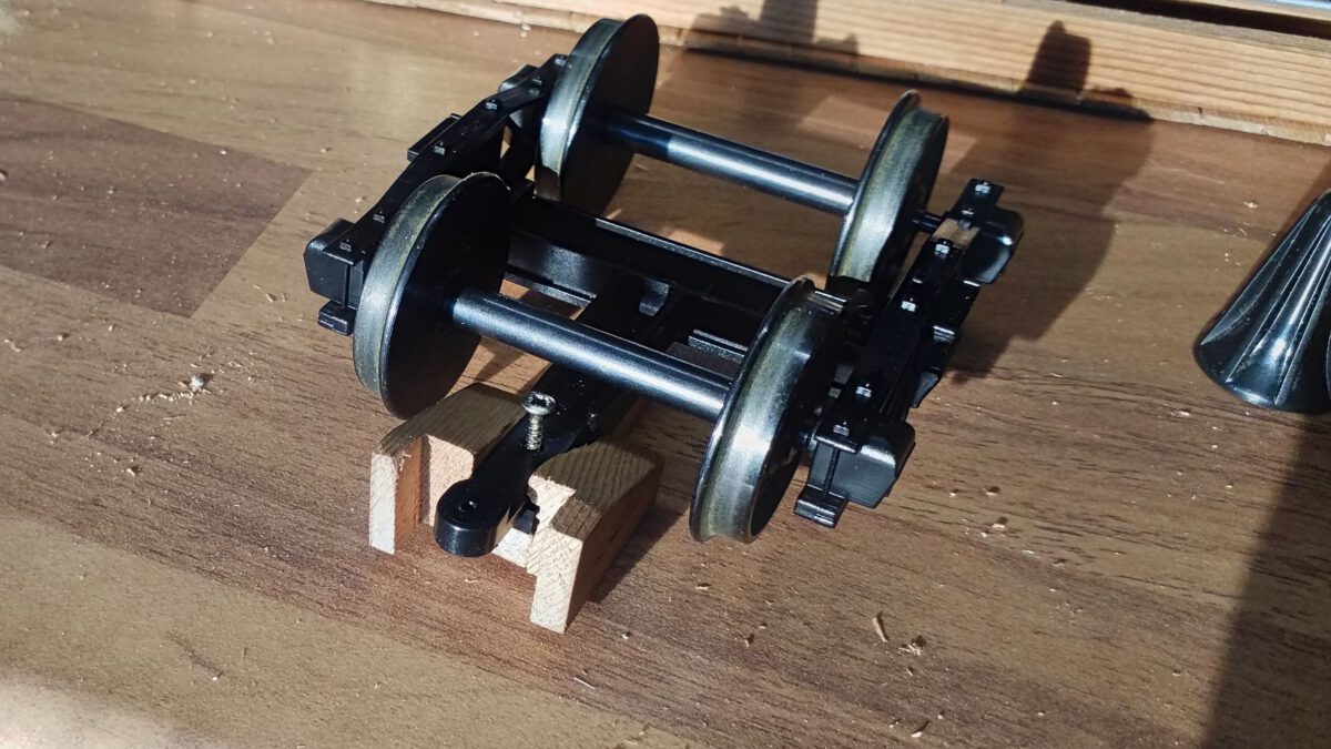
Based on my lessons learned during the last operation session, I’ve already started to mount couplers to the bogies. The result works very well, however I’m not quite happy with the looks: too clumsy, too heavy. So I’m trying a more delicate approach for the second coupler.
Flatcars Prototype: Lessons Learned from the Operation Session
Our Summer Operation Session was a lot of fun, but most of all it was informative. I learned three very important lessons concerning my flatcar prototype:
- Frame-mounted couplers need large radii
- Bogies need clearance for operational reliability
- Bogie-mounted couplers increase reliabilty
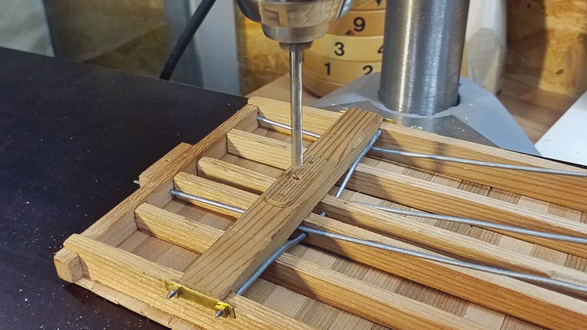
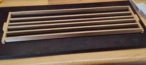
Flatcars Prototype: Floor and Trusses
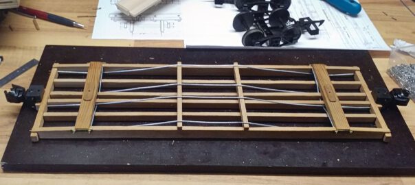
After preparing the frame and floor boards, construction can continue with the underframe. The main components are the body bolsters, needle beams and trusses. Unfortunately, I don’t have got a complete set of diagrams, so I had to guesstimate concerning the longitudinal and cross trusses. However, it’s not rocket science.
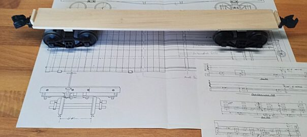
Flatcars Prototype: Materials and Frame
Based on my experiences from the flatcar experiments I’ve decided to construct a prototype for 26′ flatcars. The model is going to be built from red cedar and purchased Piko bogies.
Flatcars: Experiments
Before I start the actual construction of my planned flatcars, I’d like to know first which limits the tracks will pose on them. I’ve only ever known classic model waggons, which have their couplers on beams attached to the bogies. This design ensures high operational reliability because the couplers can follow even the tightest curve radii. However, it’s not a pretty sight.
So I’d like to build a few test waggons in order to learn how the couplers perform when attached to the waggon’s body.