
After examining the kit for the Spin construction starts swiftly. The construction manual reliably leads step-by-step through the phases. There are no blueprints and they aren’t necessary because all parts fit into each other like a 3D puzzle. First off, the fuselage.
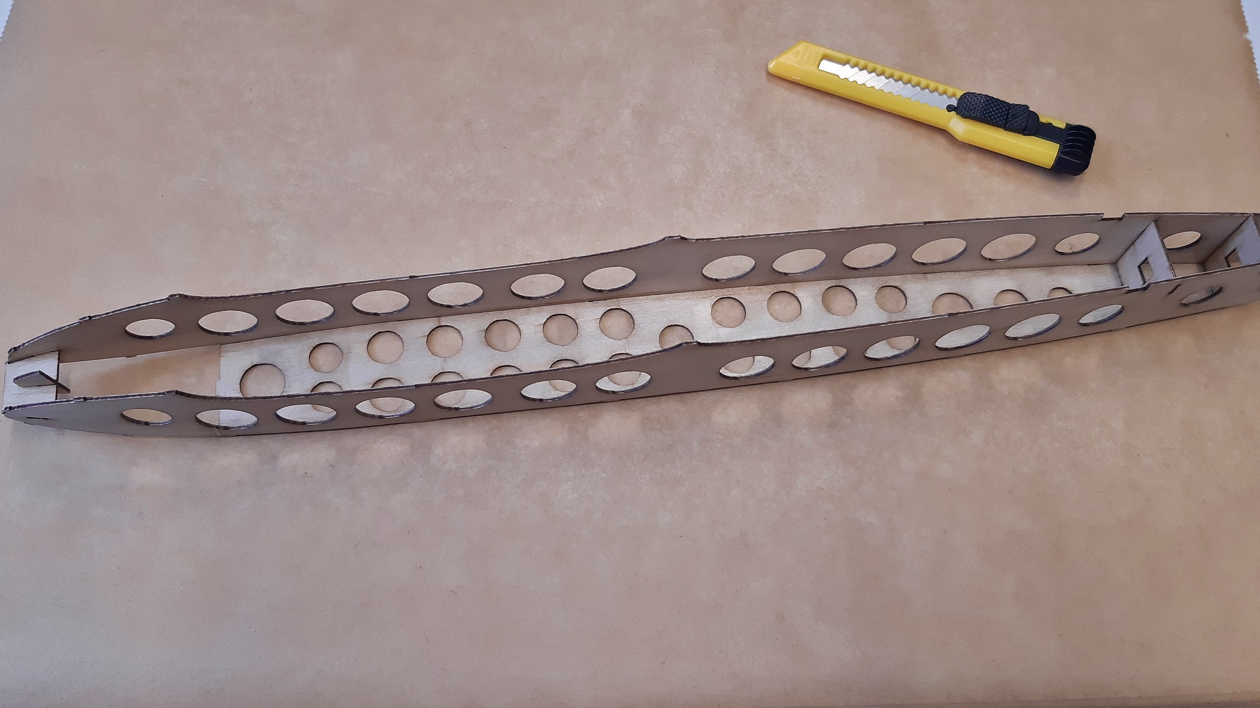
The nose is closed up by bent pieces of plywood, the manual has got some really useful hints for that. However, I didn’t just soak the wood but bent them in a small template so that there won’t be any tension within the nose.

A bit of cleaning up and this subassembly is by and large done. Now onto the wings which hold some new lessons to learn for me with their carbon fibre spar.
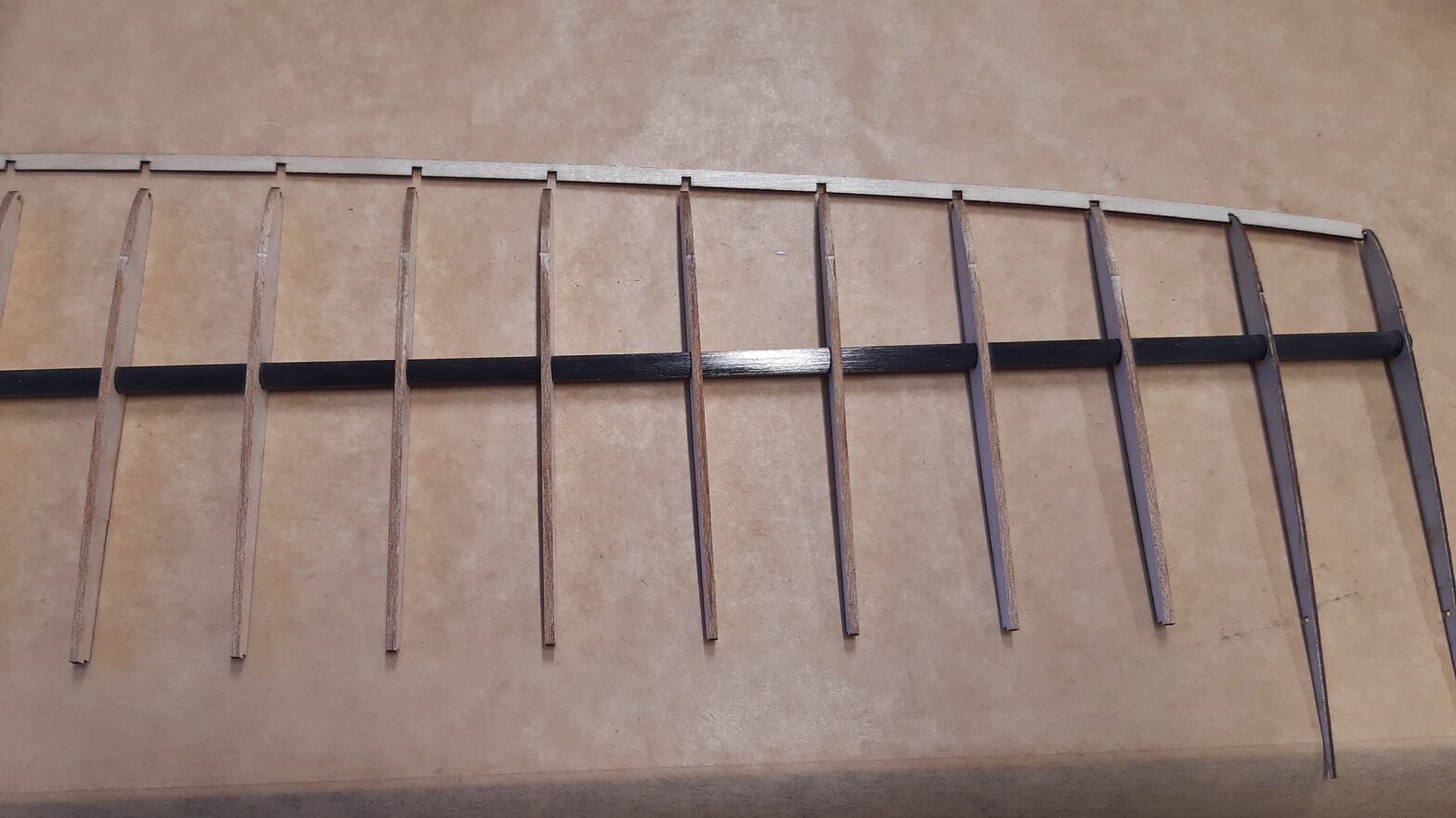
First, the ribs are threaded onto the spar and then matched to the grooves of the leading edge, which ensures the right spacing like a comb. I had some issues with glueing the ribs to the leading edge, but by working from the outside to the inside and always glueing one rib at a time while arranging the next couple of ribs in the right way, progress is possible. However one should have a keen eye on keeping all the ribs absolutely level on the baking paper. Why baking paper? That’s a new one, too: super glue doesn’t stick to baking paper and thus the working surface provides a level support.
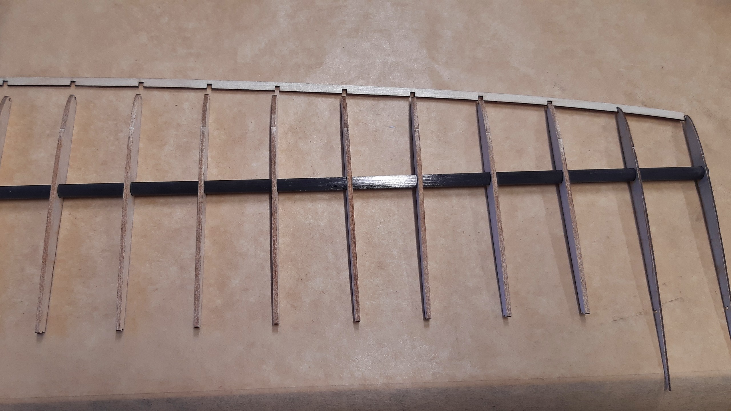
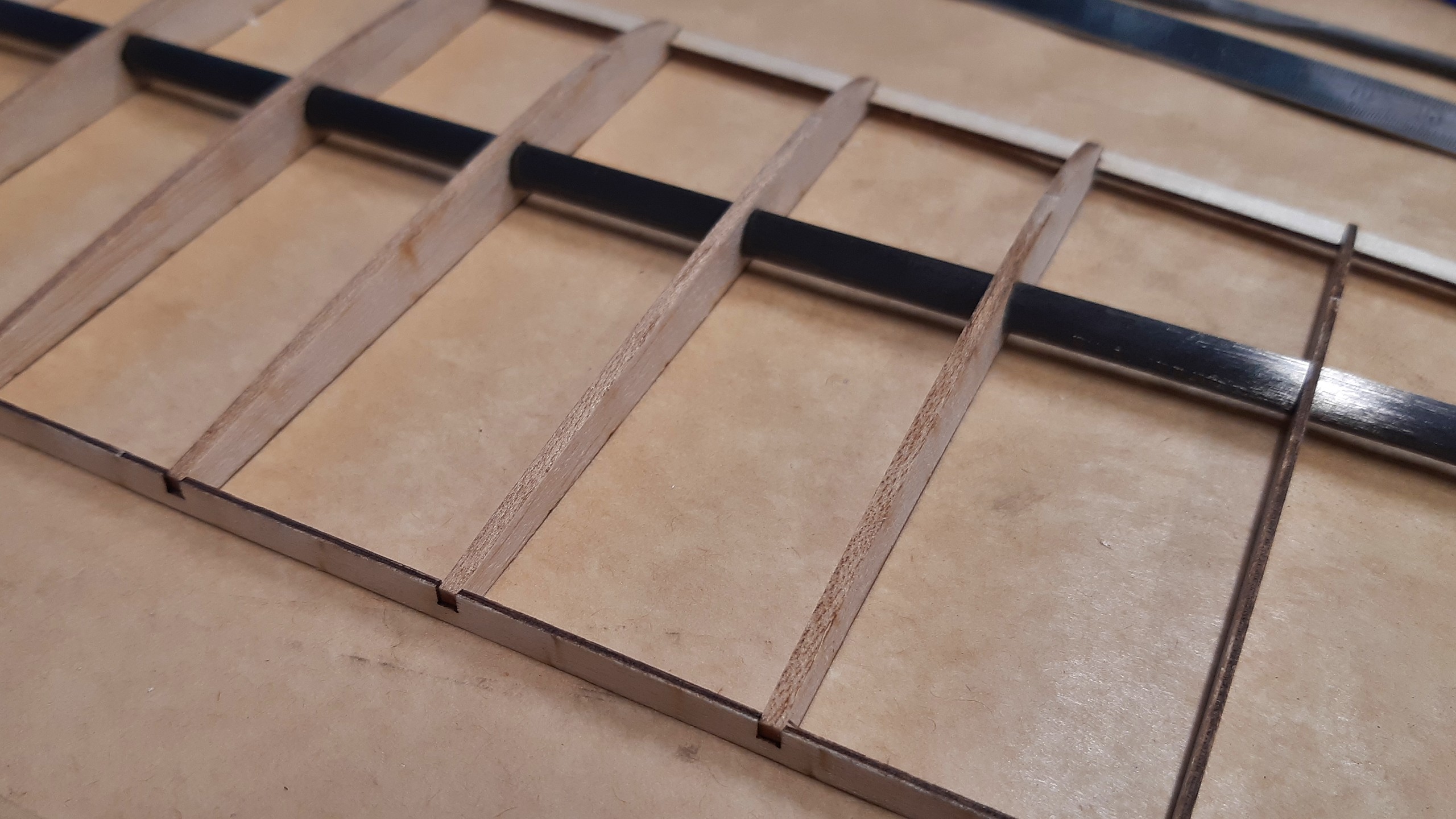
After the leading edge, it’s the trailing edge’s turn, which has grooves for the exact spacing of the ribs, too. Again, rib by rib is glued, but this time the spar is also fixed to the ribs with superglue.
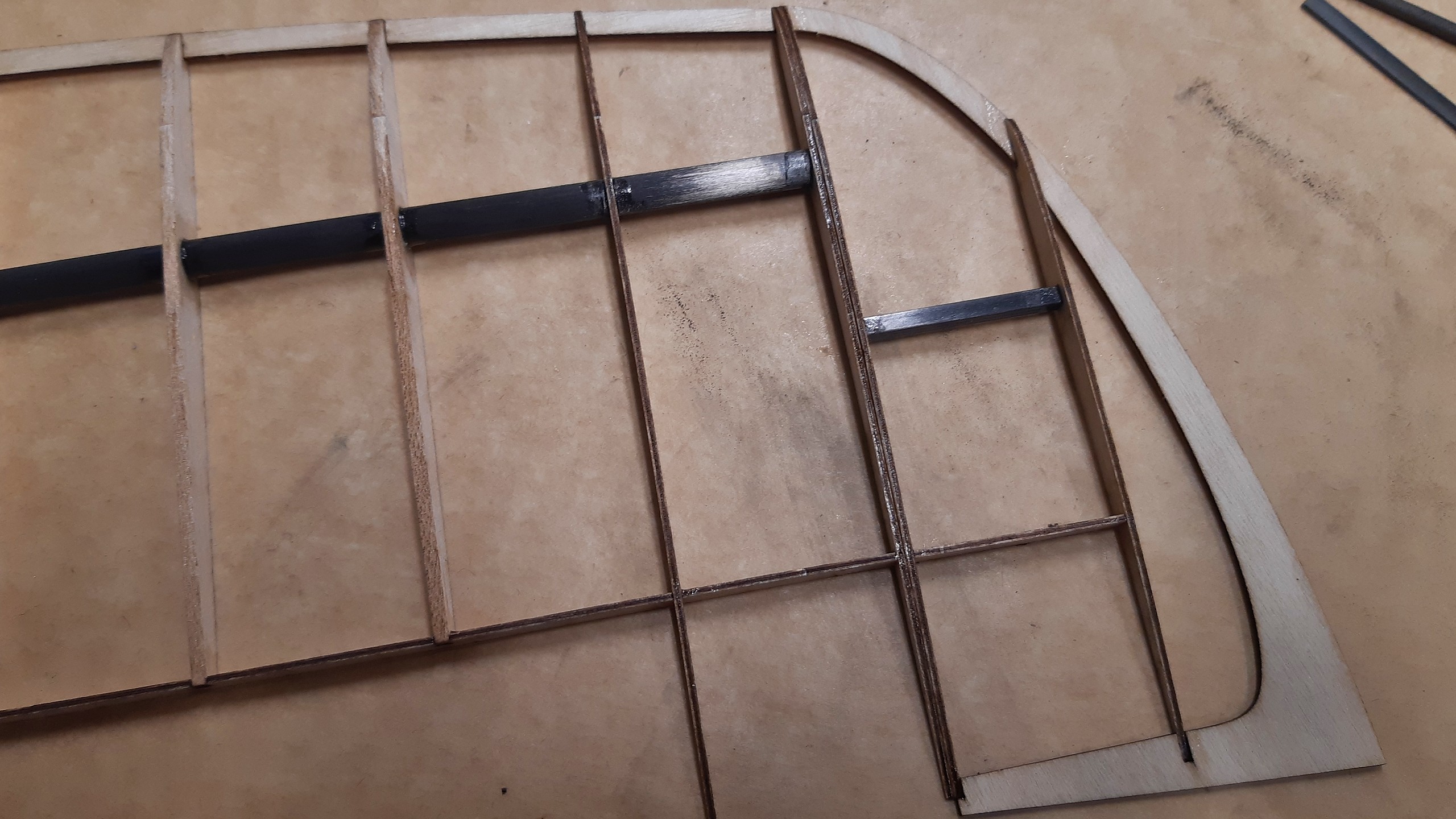
The wing tip is a subassembly in its own right and glued flush to the outer wing. The picture shows how two plywood ribs are glued back to back at the outer end of the spar. In contrast to other models I’ve seen, this wing tip is completely made from durable plywood, which will lend the durability needed for the side arm launch.
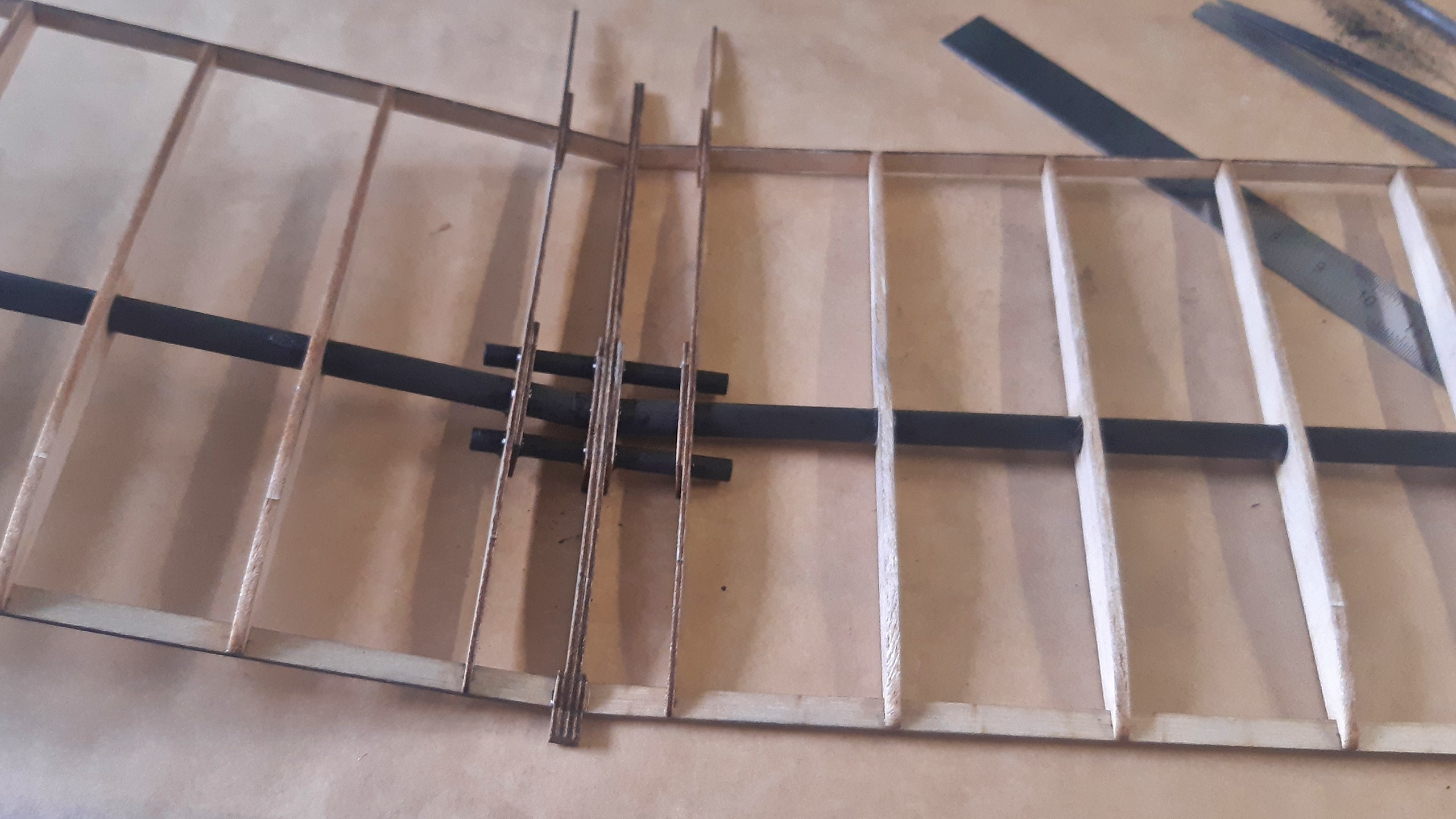
The second half of the wing is made in the same fashion and then both are connected. The design is very well-thought, so the V-shape of the wings is achieved automatically. On hindsight some part of me wishes that I’d come up with a good solution to keep the wings separable, but on the one hand I don’t want to introduce a possible point of failure into a working design and on the other hand the wings are so compact and even with the V-shape flat enough that they can easily be transported.
Next time, the empennage and preparations for covering are up.