
As I have already mentioned in my post on powering my porter loco with Li-Ion accus, I’d like to experiment with the DelTang system. There’s a lot of positive feedback from other model railroaders and all my requirements seem to be met – with further room for improvements.
Unfortunately, with the upcoming Brexit the demand for DelTang components has skyrocketed at the moment (meaining autumn 2019). I was lucky to get my hands on one Tx22 transmitter and two Rx65c receivers. It will suffice for the moment, but I will need further components, especially spares.
I bought the Tx22 as a kit, which was delivered with extensive documentation and manuals. However, one should always check the website because it provides pictures with better quality and it will be more up to date.
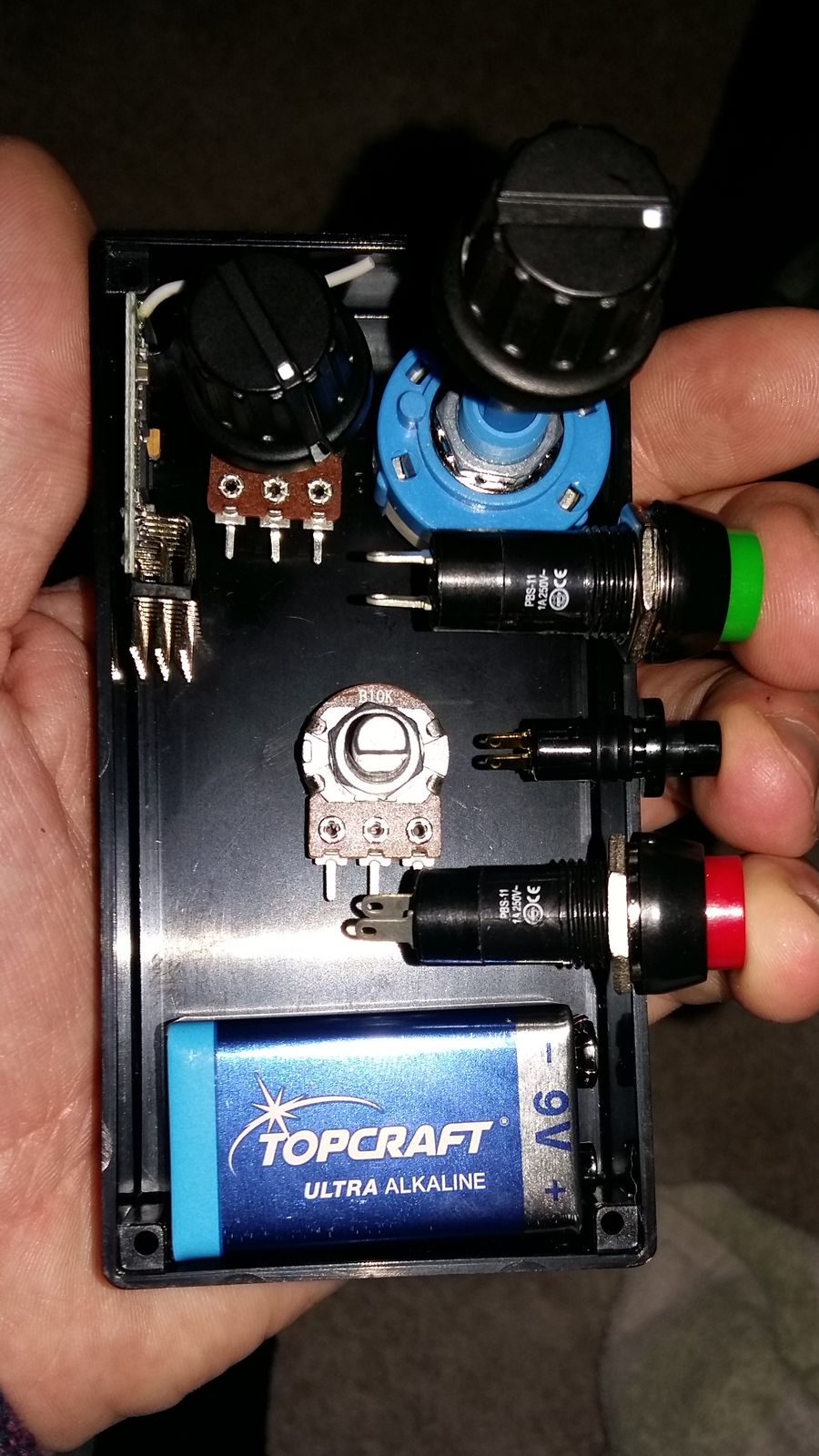
Before starting the assembly process, I spent considerable time on finding an efficient layout for the rotaries and switches. From my flight simulation experience I’m accustomed to HOTAS (Hands On Throttle And Stick), that is I want to be able to blindly reach all relevant functions without having to move my hands away from the main controls. In the end, I came up with the following layout: the speed control knob resides in the center, at the upper right is the selecta switch. Both are supposed to be controled by the right hand. To the selecta’s left is the inertia control, which I will rarely change, but in the rare event I can manipulate it with my left thumb, while my right hand controls the speed.
The switches for binding and special functions are located on the side panel. Those can handled by the left-hand fingers. The power toggle is located to the left of the speed control, where it won’t be in the way. Obviously, this is designed for a right-hander. I’m planning on building a second transmitter for left-handers, but only when the supply situation has improved and my finanical means allow such “luxuries”.
There’s one open question: I replaced the direction toggle with two buttons. It is possible that my Tx22 is designed for a latching switch and it might refuse to work with the buttons. This I can only test, but I won’t lose any sleep over this for now.
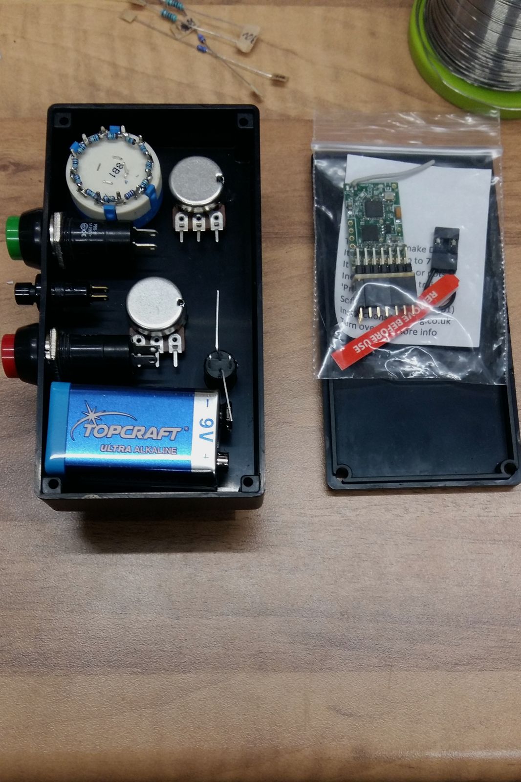
After planning was completed, the assembly started with markings for the holes. I used parcel tape to protect the surface of the box. Next time, I’ll use masking tape, it won’t leave those sticky traces…
The attentive reader is surely wondering where I will place the Tx22 circuit board. The large buttons don’t leave much space. Since I want to place the aerial in parallel with the front panel, the board will be attached to the lid. Electric connections will be achieved with flat ribbon cable and I will set up a hinge with duct tape in order to prevent mishaps when I have to open the lid (for example in order to replace the battery).
Next time, I will continue with wiring the components.
Pleased to see you’ve got your Tx22 sorted out. Soldering the resistors to the Selecta switch can be a tricky job to ensure there are no dry joints – no need to ask me how I know……
Rik
Hello Rik,
yes it’s been quite a drudge to get it all together. But thanks to your fine articles I managed to get a handle on it.