
After assembling the transmitter, I proceeded with soldering the parts. This turned out to be a fiddly affair, which kept me from taking pictures. In return, there’s a video of the final testing! 🙂
Overall one can say that the manufacturer’s documentation works very well. Once you’ve found your way around the diagrams and schemas, the assembly is easily done in a few hours’ worth of time.
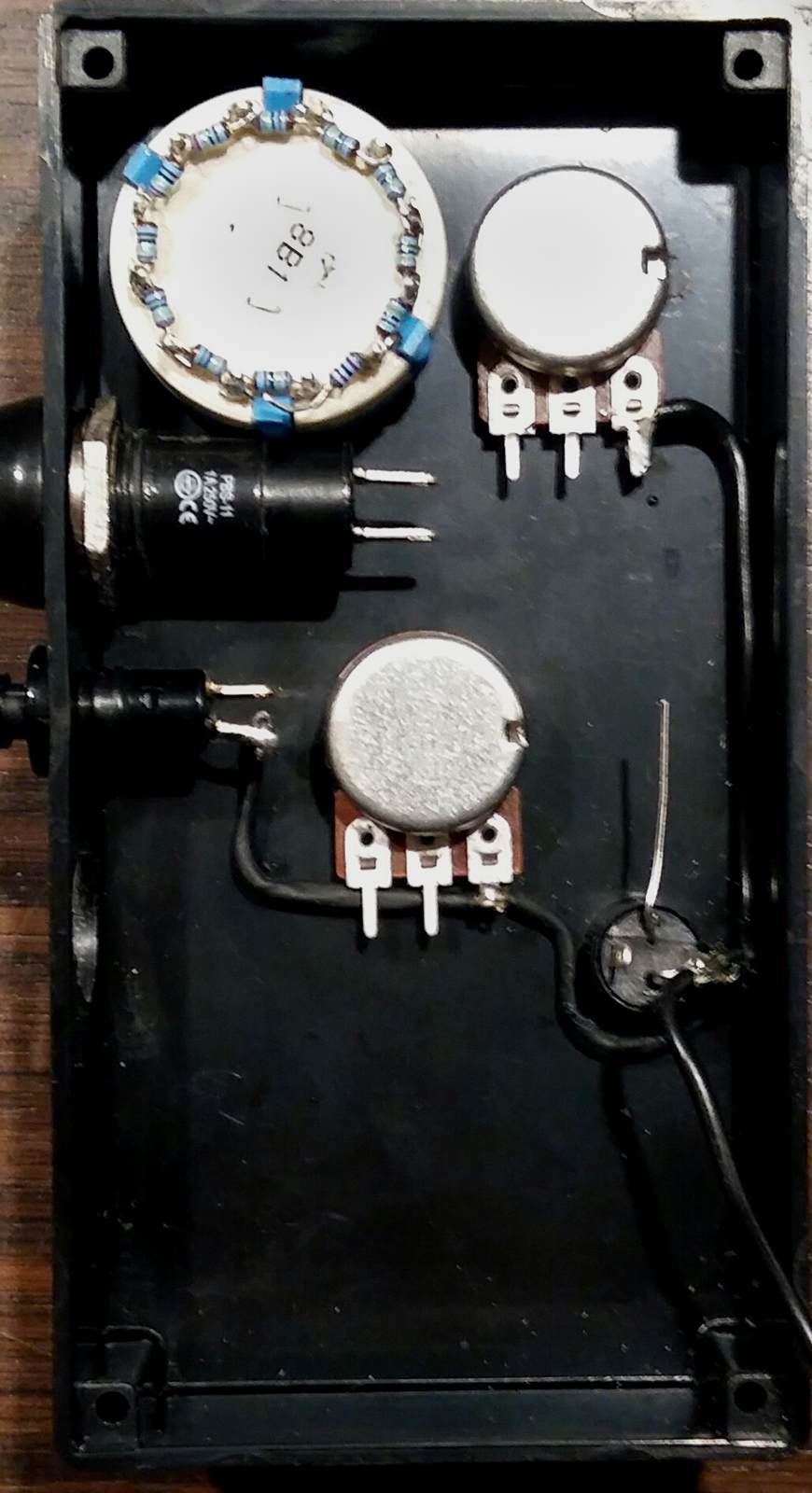
It is really helpful to plan the wiring in levels or layers. At the bottom, I placed the ground connectors. There I connected the potentionmeters, the main switch, its LED and the bind switch. The two function switches remain untouched for the moment because after soldering they will partly block access to the potentiometer.
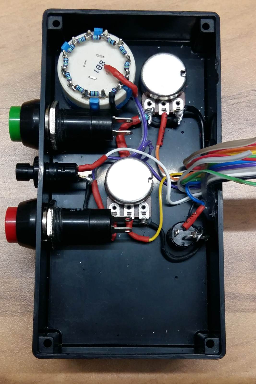
Since I will have to place the transmitter board in the lid, I used flat ribbon cable to connect the board to the parts. An additional advantage lies in the colour coding, which makes it easier to match the parts to the board connectors. That would prove to come in handy because I made two silly mistakes during assembly. We will return to that.
Each part has to be equipped with a specific dropping resistor. The switches, potentionmeter and the tap changer become identifiable by the board: each part has its own resistor. I soldered these resistors directly to the parts and covered them with shrinking tube to minimise the risk of shorts.
That way the lower level was completely wired before the quite big function switches were reinstalled. These have to be soldered in a second step.
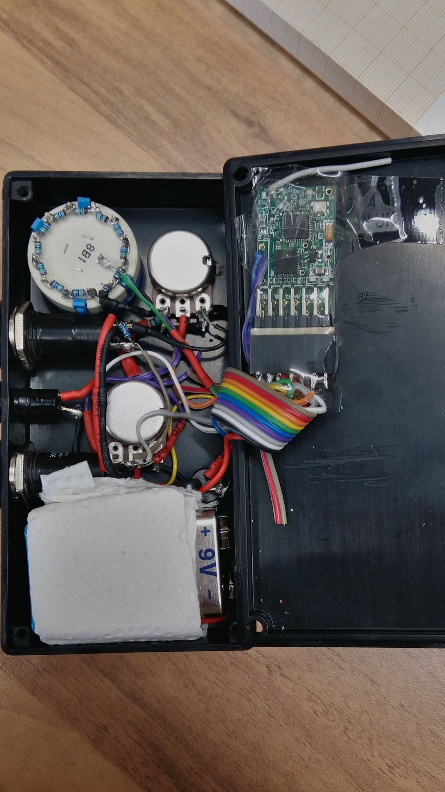
At the end, the 9V-battery has to find its place. It’s well located a the very bottom of the case because it snugly shifts the center of gravity into the hand’s palm and puts it out of the way – since the metal in the battery is able to dampen the transmitter’s signal. I soldered te battery’s ground directly to the main switch. The positive lead got a separate connection to the board.
After the soldering the first tests are possible. But one is well adviced to check the whole circuit step by step. And I promptly discovered two slips: The selecta switch was connected to the common bus of the function switches and I had managed two mix up two resistors. Fortunately, such errors are quickly fixed. The most troublesome part is removing the shrink tube.
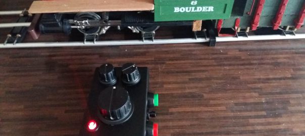
With all errors corrected, the system could be tested for basic functionality. And of course that had to ensue testing the first Rx65 receiver. Which was really the easy part: solder two cables to the power pack, complete with a power switch in between, solder two more cables to the motor outputs, connect it with the motor itself – and immediate success:
Next up will be testing special functions and including LEDs for headlights.