
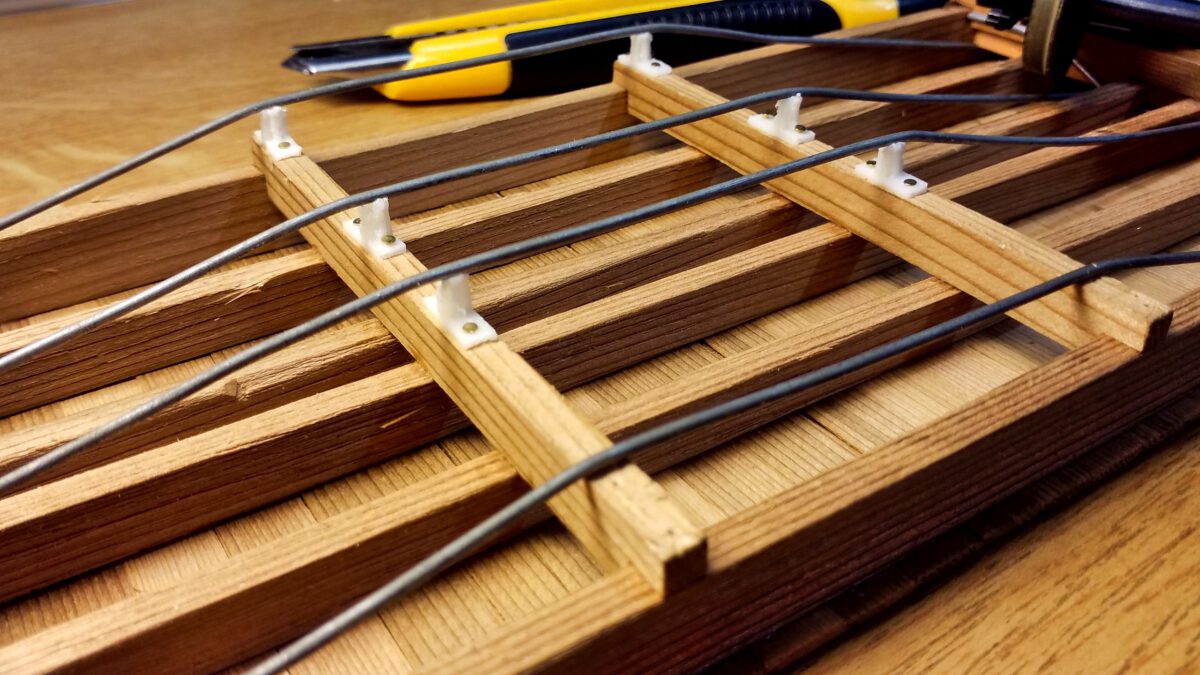
After busying myself for a while with the bogies and couplers, it’s time to start detailing the flatcar. Though they are not that striking at first glance, the details will significantly add up to the overall picture. And since they are the most visible parts, I’m starting with the trusses or more specifically the queenposts.
Tag: Frame
Flatcars Prototype: Floor and Trusses
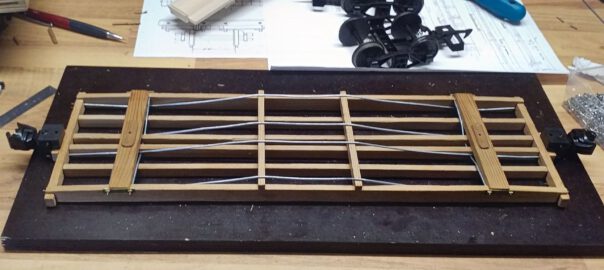
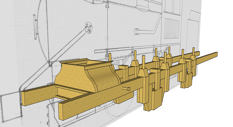
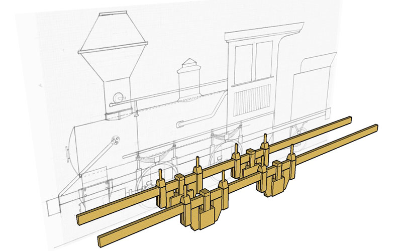
After preparing the frame and floor boards, construction can continue with the underframe. The main components are the body bolsters, needle beams and trusses. Unfortunately, I don’t have got a complete set of diagrams, so I had to guesstimate concerning the longitudinal and cross trusses. However, it’s not rocket science.
Flatcars Prototype: Materials and Frame
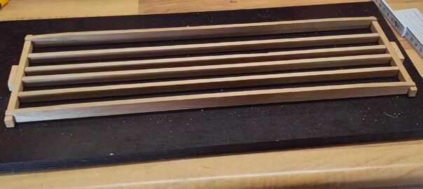
Based on my experiences from the flatcar experiments I’ve decided to construct a prototype for 26′ flatcars. The model is going to be built from red cedar and purchased Piko bogies.
Correcting the Frame
Why do I always notice such things afterwards? There I was, building the smoke saddle with trouble and care, brazing the bracket to the frame, attaching crossbeams… and then the bracket is misplaced and the whole saddle sits lopsided on the frame! -___-
Drivers Dummies
Howdy,
just a very quick update before I’m going to sleep.
I fixed the misalignment on the cylinders, thanks again Frederic from railroad-line forums for mentioning it!
Tonight I just messed around a bit and patched together some very quick’n’dirty drivers. This screenshot serves no purpose whatsoever except providing a bit of eye-candy. Enjoy!
Reconstructing the Saddle
Hello everyone,

I’m still around, though things have changed. Quit my job and found me a new one that actually leaves me some spare time. Last week I contacted Regner Dampftechnik Company in order to check up on the wheels. It seems I can expect them to arrive in late June or early July. In the meantime I took on Wallace’s advice and reconstructed the saddle. This first image shows what I’ve got so far.
Buffer Bar
Bonjour les gars,

we’ve got progress, slow but steady. Today I attacked the buffer bar. This piece is going to be quite prominent and will add to the loco’s distinctive shape, so I’d like to give it the most realistic look possible. Plus I have to be able to disassemble it whenever I have to work on the frame.
I tried some options but couldn’t think of an ideal solution.
Designing the Saddle
Hello folks,
the last weeks I’ve been strechted pretty thin between my girlfriend, our kittens and deadlines at work. However, yesterday evening I managed to squeeze in half an hour of SketchUp modeling, followed by another hour just until now.
I’m working on the connecting frame between the cylinders and the smokebox – help me out here, how is this part called? thanks to Wallace from the railroad-line.com forums I now know that this part is called the “smokebox saddle”.
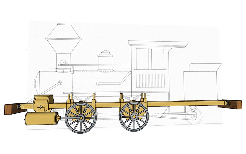
3D-Planning Commenced
Hello everyone,
just a very quick update. Work is taking over at the moment so railroad has to take a step back. However I managed to start on the 3D model, here’s the status quo:
See you around soon!