Workshop: Cross Cut Sled for the Miniature Table Saw

The runners' glue is curing.

As I mentioned in the construction report, I made a mistake while building the vertical stabilizer for my biplane, namely not chafing the trailing edge. Attempting to correct this using the transverse stop thoroughly failed. In order not to have to repeat this experience, I’m building a cross cut sled for the circular table saw.

However, a cross cut sled is capable of many more things. For once it facilitates to repeatively cut slats to length, thus one can skimp on a mitre saw. And then one can use it to get small boards back to right angles which were cut crookedly, so they can be rip cut again. So today is about the first part of a mini project which will facilitate my other handicraft.

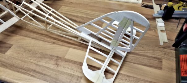
Joyrider: Tailplane Assembly

Construction is finished.

Finishing the vertical stabilizer only leaves the tailplane’s assembly. Here, three important objectives have to be met: the horizontal stabilizer must be in parallel to the long axis, so must the vertical stabilizer, and the vertical stabilizer has to be at right angles to the horizontal stabilizer.

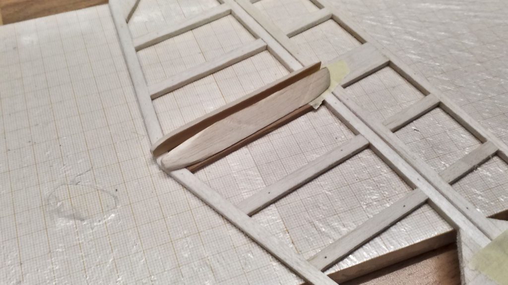
The most important contribution to the right angles is provided by clean, perpendicular cuts, which I can achieve easily thanks to my table saw. In order to further stabilize this orientation, I’ve constructed two guides from balsa wood and sanded them into a streamlined shape.

The vertical stabilizer's guide is in progress.
The vertical stabilizer’s guide is in progress.

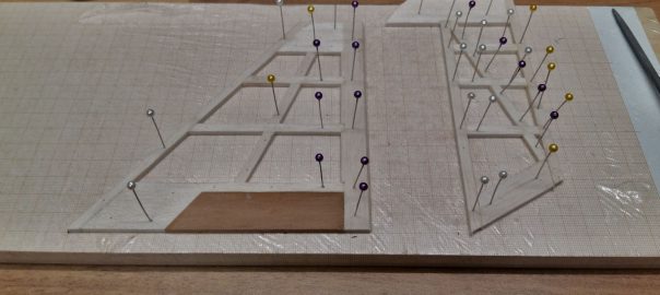
Joyrider: Vertical Stabilizer

Before sanding the tip.

The structural work is coming to and end: since the horizontal stabilizer has made much progress, it’s the vertical stabilizer’s turn.

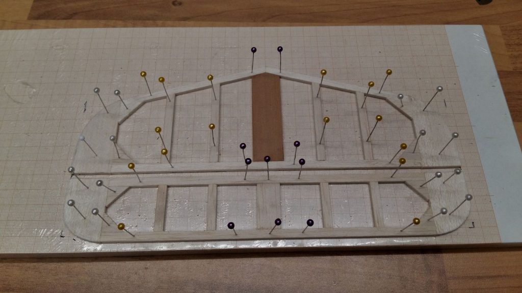
Horizontal stabilizer and elevator reinforced.

Horizontal stabilizer and elevator reinforced.Even while building the horizontal stabilizer I realized I made a design error: the thin leading and trailing struts have been glued to the tips as butt joints, lacking adhesion area and thus stability. I rectify this by reinforcing the corners with small wedges of balsa wood. And this enlightment directly flows into the vertical stabilizer.

Joyrider: Horizontal Stabilizer

The landing gear’s completion left only one step to finish the structural work: the tailplane. I copped out for a while to face this step because the tail plane ultimately makes or breaks the aircrafts stearability:

If it’s too small, you can’t control the model aircraft. If it’s too big, the bird responds like a proper boulder. This effect is additionally influenced by the fuselage’s length, as I’ve already mentioned while building the fuselage. That’s why I’m really glad to have found Christian Forrer’s web site, including an excel sheet for calculating model dimensions, before I started constructing my biplane in earnest. Based on the finished parts, I was able to determine the minimum size for the tail plane and get on with it.

Winter Operation Session 2020

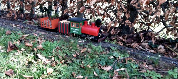
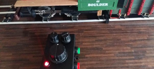
01 Porter pulling 101 Stake Wagon.

Last Saturday, an old friend of mine and I held a small operation session at his place. The weather was fabulous, we had high temperatures for february, around 14°C and lots of sunshine.

It’s been a huge success: multiple trains running simultaneously, shunting, test drives, lots of talk on lots of topics. But most important: a train-load of fun!

Shunting Dice for Operating Sessions

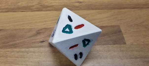
Triangles glued, body painted.

The operation session which a good friend of mine and I are planning is approaching. It’s going to be a premiere in more than one aspect: we haven’t done joint operations for a long time; it’s also been a long time since we did some shunting; and we’re going to try and let children participate.

So the question stands: How can we combine interesting operations with as few rules as possible and as little preparations as possible? Enter *drumroll* the shunting dice.

Timber Cargo for Bulkhead

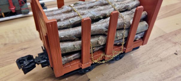
Loaded and secured.

In preparation for the next driving session at a friend’s of mine, I focused on Bulkhead #101. (By default, which other waggons do I possess right now?)

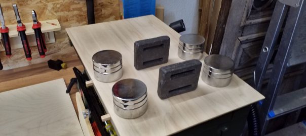
The little darling is supposed to serve as a coupling adapter (knuckle coupling at the front, LGB’s “bottle opener” at the rear). So that it can excel in the task, the waggon needs some additional weight, which I provided by means of a timber load. And in order to keep the latter in place, some fastening had to be added.

Porter and Tender: Coupling-Maintenance

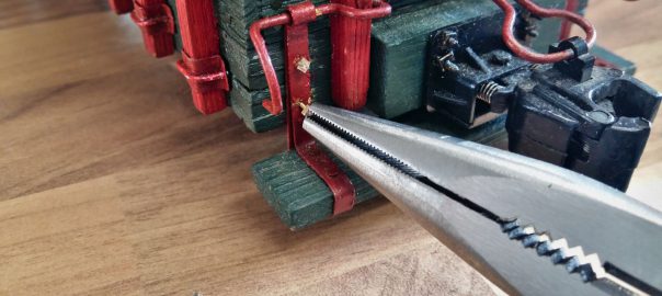
Threaded rods are screwed into the wood.

My faithful Porter had some work to do during this winter, for which it was transported to different places: Into the garden, at my parents-in-law’s, even at work. Of course, these transports always entail boxing and unboxing into transport crates, which lead to considerable wear regarding the coupling between loco and tender on the one hand, and the conductor’s platform at the tender’s rear end on the other hand. Thus, we’re going to focus today on ever-occuring maintenance and possible improvements.

Joyrider: Undercarriage

With the fuselage finished it’s time to focus on the undercarriage. I’ve got two major objectives concerning my model: I want to have the capability to take off from smooth runways and I need a suspended undercarriage in order to dampen jolts during landings.

That’s quite an order on such a small model. Since I don’t want to put tundra wheels on a biplane, I probably won’t even be able to take off from mowed grass runways, but tarmacs should do. As a principle I don’t want to omit the undercarriage because on the one hand it offers some protection to the propeller and on the other hand it’s just part of a prototypical look. In fact I only know of one biplane with retractable gear, that being the Polikarpov I-153 “Chaika”.

Deltang Tx22 Completion

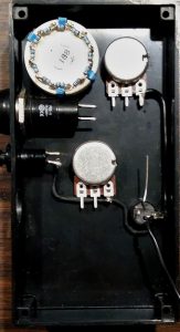
Wiring the ground first.

After assembling the transmitter, I proceeded with soldering the parts. This turned out to be a fiddly affair, which kept me from taking pictures. In return, there’s a video of the final testing! 🙂

Overall one can say that the manufacturer’s documentation works very well. Once you’ve found your way around the diagrams and schemas, the assembly is easily done in a few hours’ worth of time.

It is really helpful to plan the wiring in levels or layers. At the bottom, I placed the ground connectors. There I connected the potentionmeters, the main switch, its LED and the bind switch. The two function switches remain untouched for the moment because after soldering they will partly block access to the potentiometer.